


3.4 OFFSETS Screens
39
For detailed description of work offset measure see the chapter 7.2.1 “Work Offset Mea-
sure” on the page 76.
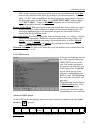
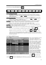
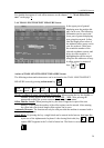
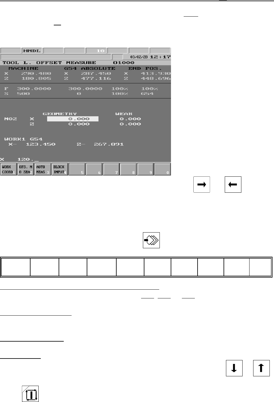
3.4.4 TOOL LENGTH OFFSET MEASURE Screen
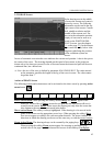
In the upper part of general
displaying area the position dis-
play can be seen. The following
information can be seen in the
lower part of general displaying
area going downwards. In line
Nnn the length offset values of
the indicated offset group can be
seen for each axis. In the next
line stands the number of the
selected coordinate system, and
below its offset registers. A
highlighting bar can be moved
along the axis addresses of leng-
th offset register by means of
keys and .
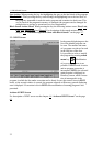
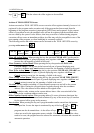
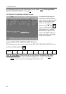
Actions of TOOL LENGTH OFFSET MEASURE Screen
The following actions and action menus can be activated to the TOOL LENGTH OFFSET
MEASURE screen by pressing action menu key :
Work
coordnt1
Ofs No
search 2
Auto
meas 3
Single
block 4 5 6 7 8 9 0
Work Coordinate System Action Menu (Work cld):
When pressing the key the eligible co-
ordinate systems appear in the menu bar: G54, G55, ... G59. After pressing the
appropriate softkey the system returns to first level of action menu.
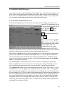
Offset Number Search: When pressing the key the letter N appears in spite of the axis
address. At this point the number of the offset register can be entered. After entering
the offset index the desired length offset register can be seen.
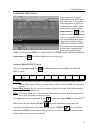
Automatic Measure: The function can only be used provided the machine is mounted with a
tool length sensor.
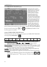
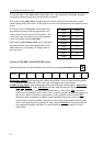
Single Block: By pressing the key a single block can be entered in the bottom, data input line
by the use of the alphanumeric keyboard. After closing block edit (key or )
caption SBEX appears in the 2
nd
field of status bar. The block is executed with START
.