


7.2.4 Calibrating Tool Offset Sensor
82
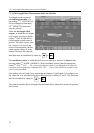
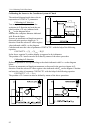
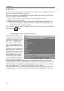
Calibrating the Sensor to the Coordinate System of Chuck
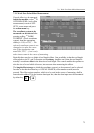
The enclosed diagram beside shows the in-
terpretation of CONTACT parameters.
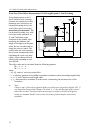
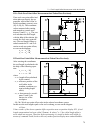
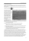
Calibrating in X direction
Turn an optional workpiece, leave the
workpiece in Z direction and read the ma-
chine position of X axis, indicated with
X
workp
on the diagram below.
Measure the workpiece diameter indicated
with D on the figure.
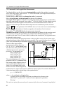
Execute an automatic tool length measure as
discussed in the previous chapter in X–
direction. Read the selected X offset register
value indicated with X
(–)
on the diagram.
Calculate and enter the value of parameter CONTACTX– with the help of the following
equation:
CONTACTX– = [X
(–)
– (X
workp
– D)]/2
In the above equation X position display is supposed to be in diameter.
The position of X+ button can also be defined by means of the above procedure
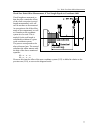
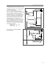
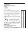
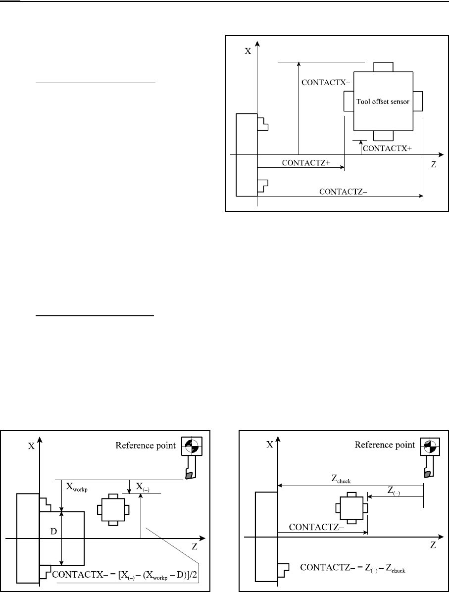
Calibrating in Z direction
Define the position of tool tip according to the chuck indicated with Z
chuck
on the diagram
below.
Execute an automatic tool length measurement as discussed in the previous chapter in Z–
direction. Read the selected Z offset register value indicated with Z
(–)
on the diagram. Calculate
and enter the value of parameter CONTACTZ– with the help of the following equation:
CONTACTZ– = Z
(–)
– Z
chuck
The position of Z+ button can also be defined by means of the above procedure.