


Troubleshooting
900-0020-01-00 Rev A 35
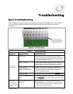
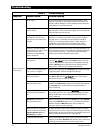
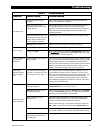
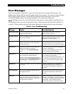
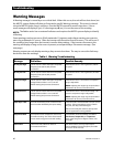
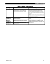
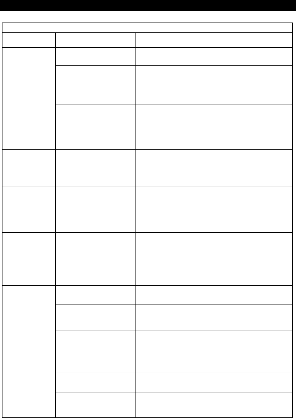
Table 2 Troubleshooting
Symptom Possible Cause Possible Remedy
Charge complete or nearly
complete.
Check the DC voltage and charging stage using the MATE3, if
present. Confirm with DC voltmeter.
MATE3’s DC meter reads
significantly higher than actual
battery voltage.
Check the DC voltage on the inverter’s DC terminals. If different
from the MATE3 reading, the inverter could be damaged.
Otherwise, check the DC voltage on batteries with a voltmeter. If
different from the reading on the inverter, this could be a DC
connection problem.
High output loads. If total loads
and charge exceed the AC input
setting, charge rate decreases
to give priority to the loads.
Turn off some of the output loads and test the charge rate again.
Low charge rate.
Generator
input mode in use.
Radian charge rate is limited in this mode (see page 9.)
No AC input. See “Will not connect to AC” category.
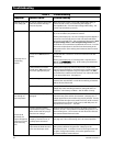
Will not charge.
Charger set to
Off
. MATE3 system display only: Check the
Charger Mode
screen with
the
CHARGER
hot key and set to
On
or
Auto
. (If this setting was
intentional, then no action is required.)
Unusual voltage on
hot or neutral
output line.
System neutral and ground may
not be bonded.
Test L1 OUT, L2 OUT, and NEU test points with AC voltmeter. (See
page 33.) These measurements should give full voltage. Test NEU
and ground connections. This measurement should read zero
volts. Any other result means neutral and ground are not bonded
correctly. If this is the case, usually the hot line reads 60-75 Vac
and the neutral reads 45-60 Vac, with respect to ground.
Unusual and
different voltages
on AC hot input
lines.
Input neutral is not connected
correctly. The inverter also may
not connect to the AC source.
Test L1 input and NEU connections with AC voltmeter. Test L2
input and NEU connections with AC voltmeter. (This can be on
Grid or Gen input, depending where the symptoms appear.) Test
L1 to L2 input. From hot to neutral should be approximately
120
Vac. L1 to L2 should be approximately 240 Vac. If the two
legs are different voltages but still add up to 240 Vac, the neutral
is not connected to the inverter.
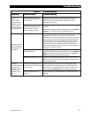
Grid-tied function has been
manually disabled.
MATE3 system display only: Check the
Grid-Tie Enable
setting in
the
Grid-Tie Sell
menu. Confirm it is set to
Y
.
Grid Tied
mode not in use on
the appropriate input.
MATE3 system display only: Check the
Inverter
part of the
Settings
menu to see if
Grid Tied
mode is in use. Confirm that it has been
selected for the correct Radian input terminals.
AC source does not meet
requirements.
Verify grid voltage and frequency. Determine if they are within
the inverter’s approved limits. If not, the inverter is behaving
correctly. Contact the utility company if necessary.
MATE3 system display only: The program selections for limits are
IEEE
or
user
. They are found in the inverter’s
Grid-Tie Sell
menu.
Inverter priority.
MATE3 system display only: Check
Sell Status
screen using the
Home screen’s soft keys. The inverter may be behaving correctly.
Will not sell power
to the utility grid.
High output loads will consume
power before it is returned to
the utility grid.
Turn off some output loads and observe the sell function.