


15
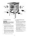
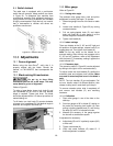
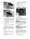
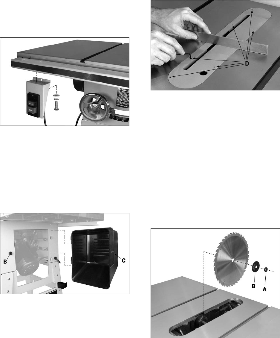
8.10 Switch bracket
Refer to Figure 13.
Remove existing screw and washers from the
farthest left hole on the guide tube, and use them
to secure the control switch to bottom of guide
tube, as shown in Figure 13 (10mm wrench).
Figure 13
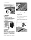
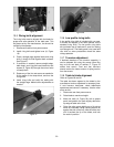
8.11 Motor cover
Refer to Figure 14.
1. At the motor side, slide the hinge pins of the
motor cover down into the cylinders.
2. To secure cover, loosen knob (B), and swing
cover shut, while pushing in on the side. The
slot (C) should slide beneath the knob.
3. Tighten knob (B).
Figure 14
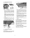
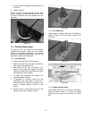
8.12 Table insert
Refer to Figure 15.
Place insert into table opening (the finger hole is
toward front of saw). Verify that insert lies flush
with table surface by resting a straight edge across
it at various points. If insert is not flush along its
length, turn any of six set screws (D) to raise or
lower that area of the insert.
NOTE: If while lowering blade, the points on the
anti-kickback pawls tend to catch in the seam
between table and table insert, slightly raise that
area of the table insert above main table surface.
Figure 15
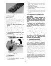
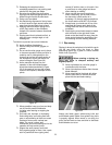
8.13 Installing and removing blade
A blade is not provided with the 64B.
1. Using front handwheel, raise blade arbor fully
and tighten lock knob.
Refer to Figures 16 and 17.
2. Remove nut (A) and flange (B), and install
blade onto arbor, making sure the teeth point
downward toward front of saw.
3. Install flange (B) and nut (A).
4. Rotate arbor until hole (C, Figure 17) aligns
with arbor lock pin (D). Push tab (E) to seat pin
into hole, and hold to prevent blade rotation.
5. Tighten nut (A) with arbor wrench.
6. Release arbor lock (E).
Figure 16