


18
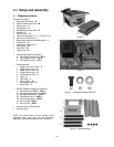
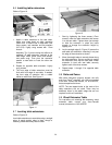
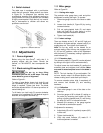
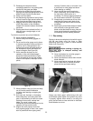
9.4 Switch lockout
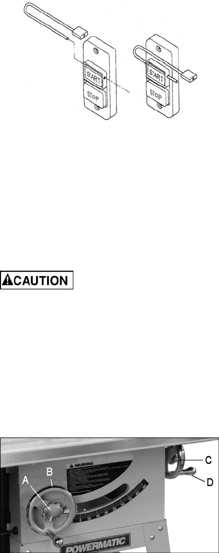
The table saw is equipped with a push-button
switch that will accept a safety padlock, as shown
in Figure 20. To safeguard your machine from
unauthorized operation and accidental starting by
young children, the use of a padlock (not included)
is highly recommended. Place the key in a location
that is inaccessible to children and others not
qualified to use the tool.
Figure 20: Switch Lock Out
10.0 Adjustments
10.1 Fence alignment
Before using the Accu-Fence
®
, verify that it is
properly aligned with the blade. Consult the
manual, no. M-2195075Z, that accompanied the
fence.
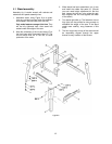
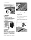
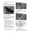
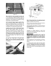
10.2 Blade raising/tilt mechanism
Do not try to force tilting
mechanism past the 45º or 90º stops. This may
cause blade to go out of alignment.
Refer to Figure 21:
To raise or lower blade, loosen lock knob (A) and
turn handwheel (B) on front of saw until desired
height is reached. Tighten lock knob. The blade
should be adjusted about 1/8" above top surface of
material being cut.
To tilt blade, turn lock knob (C) counter-clockwise
to loosen, turn handwheel (D) until desired angle is
obtained, and retighten lock knob (C).
Figure 21
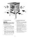
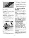
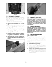
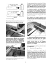
10.3 Miter gauge
Refer to Figure 22.
10.3.1 Setting miter angle
The precision miter gauge has a rack and pinion
adjustment for setting the angle. To operate:
1. Slide miter gauge into one of the slots on table
top.
2. Loosen lock handle (A, Figure 22) by turning
counterclockwise.
3. Pull out spring-loaded knob (C) and rotate
knob until body (B) of miter gauge is at the
desired angle as indicated on the scale.
4. Tighten lock handle (A).
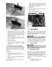
10.3.2 Indent settings
There are indents at the 0º, 30º and 45º right and
left positions. At these settings, release knob (C) to
engage stop rod. Then tighten lock handle (A).
Note: Do not rely solely on the indents for an
accurate setting. After the stop rod engages at the
0º, 30º and 45º positions, make a fine adjustment
with the knob (C) if necessary, setting it against the
scale indicator (G).
10.3.3 Extension plate
The extension plate (D, Figure 22) can be adjusted
by sliding to the right or left or removed entirely.
To adjust, loosen two lock handles (E), position the
extension plate and retighten lock handles. Make
sure end of extension plate is not in the blade’s
path.
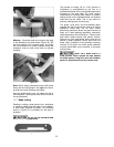
NOTE: The lock handles (E) are adjustable. Pull
out on a handle, rotate it to different position, then
release, making sure it seats itself upon the pin.
To remove extension plate, slide it completely off
and remove lock handles (E) and mounting
hardware.
10.3.4 Calibration
1. Place miter gauge in one of the slots on the
table top.
2. Set miter gauge at 90º to blade (0º setting on
the scale) by loosening lock handle (A), then
pulling out spring-loaded knob (C) and turning
the body (B) until 0º is indicated on scale.
3. Measure the accuracy of the gauge against
the slot with a combination square.
If adjustment is necessary:
4. Adjust body (B) until it is perfectly square (90º)
to miter slot.
5. Tighten lock handle (A).
6. Verify that scale indicator (G) reads 0º. If
further adjustment is needed: