


10
Installation
Tools required for assembly and set up:
7/32” hex (Allen) wrench
6mm hex (Allen) wrench
12mm open-end wrench
Square
Hoist or forklift, with straps
Remove all crating and plastic from around the
machine. Remove any screws or straps holding
the band saw to the shipping pallet.
Exercise care when
removing the machine from the shipping
pallet.
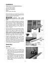
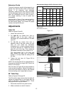
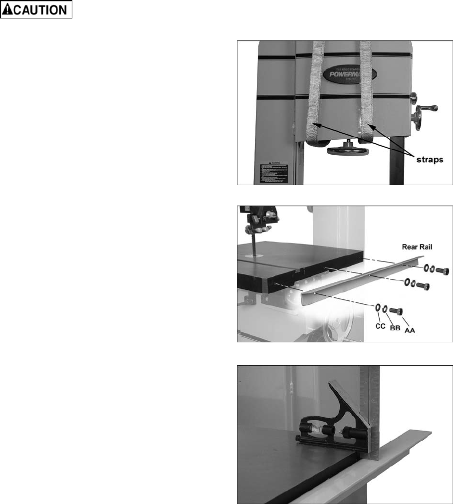
Use a hoist or forklift with straps to remove the
machine from the pallet. The straps used should
have a minimum 1,000 lb. lifting capacity. Do
NOT place forks or straps directly beneath the
table or against handles or levers - place the
straps under the top portion of the frame, as
shown in Figure 3.
Move the band saw to its permanent location,
which should be dry and well lit, with enough
space on all sides to handle long stock or
perform routine maintenance on the machine.
Make sure the floor is able to support the weight
of the machine. If desired, the band saw can be
secured to the floor using lag screws (not
provided) through the four holes in the base.
Exposed metal surfaces, such as the table
surface and blade guides, have been given a
protective coating at the factory. This coating
should be removed with a soft cloth moistened
with solvent. Do not get solvents near plastic or
rubber parts; and do not use an abrasive pad as
it may scratch the exposed surfaces.
Assembly
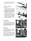
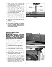
Rear Rail
Refer to Figures 4 and 5.
1. Install the rear rail to the rear edge of the
table, using three 5/16-18 x 3/4 hex cap
screws (AA), three 5/16 lock washers (BB),
and three 5/16 flat washers (CC) as shown.
Hand tighten only.
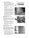
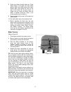
2. The exact distance from rear rail to table top
is not important, but the rear rail should be
made parallel to the table top. Place a
measuring device, such as a combination
square (Figure 5) at front and back of the
table as shown.
Figure 3
Figure 4
Figure 5