


15
Extension Cords
The use of extension cords is discouraged; try to
position the machine within reach of the power
source. If an extension cord becomes
necessary, make sure the cord rating is suitable
for the amperage listed on the machine’s motor
plate. An undersized cord will cause a drop in
line voltage resulting in loss of power and
overheating.
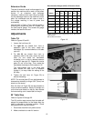
Use the chart in Figure 19 as a general guide in
choosing the correct size cord. If in doubt, use
the next heavier gauge. The smaller the gauge
number, the heavier the cord.
Adjustments
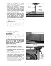
Table Tilt
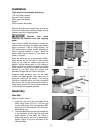
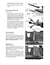
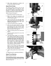
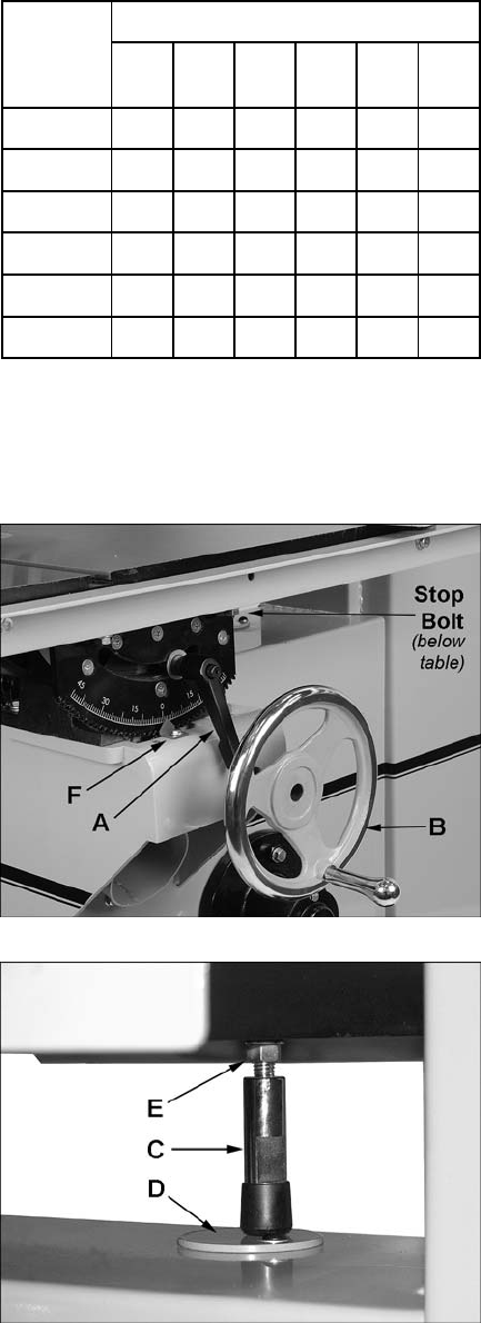
Refer to Figures 20 and 21.
1. Loosen the lock lever (A).
2. For right tilt (as viewed from front or
operator’s side of the saw), rotate the
handwheel (B) counterclockwise to tilt table
up to 45°.
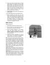
3. For left tilt (as viewed from front or
operator’s side of the saw), loosen the lock
lever (A) and rotate the handwheel
clockwise a turn or two to release pressure
on the 90° stop bolt (C). Rotate the circular
plate (D) out of the way. Then rotate the
handwheel clockwise to tilt the table to 15°.
The now-exposed hole in the band saw
body allows the stop bolt to descend
through it, to keep intact the setting of the
90° stop.
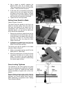
4. Tighten the lock lever (A, Figure 20) to
secure the setting.
NOTE: The circular plate (D) can be tightened or
loosened as desired by using a 5/32” (4mm) hex
wrench on the screw.
Also, the lever (A, Figure 20) can be pivoted to a
more convenient position. Simply lift straight out
on the lever and rotate it on the pin, then release
the lever making sure it seats itself on the pin.
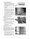
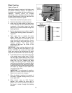
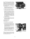
90° Table Stop
Refer to Figures 20 through 22.
The 90° positive stop ensures that the table will
always be perpendicular to the blade after the
table is returned to horizontal position. Check
and adjust this 90° stop as follows:
1. Disconnect machine from power source.
2. Make sure blade is under full tension.
Recommended Gauges (AWG) of Extension Cords
Amps
Extension Cord Length *
25
feet
50
feet
75
feet
100
feet
150
feet
200
feet
< 5 16 16 16 14 12 12
5 to 8 16 16 14 12 10 NR
8 to 12 14 14 12 10 NR NR
12 to 15 12 12 10 10 NR NR
15 to 20 10 10 10 NR NR NR
21 to 30 10 NR NR NR NR NR
*based on limiting the line voltage drop to 5V at 150% of the
rated amperes.
NR: Not Recommended.
Figure 19
Figure 20
Figure 21