


11
Adjustments
When changing tools, making
adjustments, or doing clean-up and
maintenance, always turn the machine off and
unplug the machine from its power source.
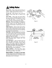
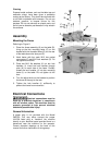
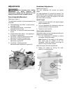
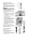
Fence Assembly Movement
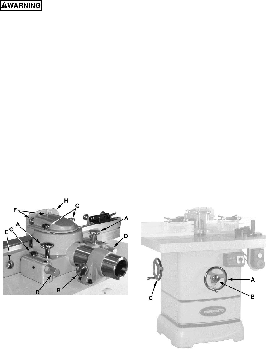
Referring to Figure 4:
The adjustment controls of the fence assembly are
as follows:
A – Fence Assembly Lock Knob – to secure fence
assembly to table
B – Fence Adjustment Knob – moves fence
assembly forward or back
C – Lock Knob – to secure the infeed and outfeed
fences
D – Infeed/Outfeed Ram Adjust – fine adjustment
for infeed or outfeed fence
E – Lock Knob – loosening permits side to side
adjustment of infeed or outfeed fence
F – Lock Knob – loosening permits vertical
adjustment of guard (H)
G – Lock Knob – loosening permits
backward/forward adjustment of guard (H)
Figure 4
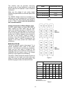
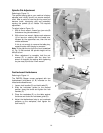
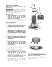
Handwheel Adjustments
Referring to Figure 5:
The front handwheel (B) controls the spindle
height.
The side handwheel (C) controls the casters. The
Model PM2700 has a retractable caster system that
can be extended to permit the shaper to be rolled
from one location to another.
Spindle height
1. Loosen the lock knob (B) on the spindle height
adjust handwheel (A).
2. Turn the handwheel (A) clockwise to raise and
counterclockwise to lower the spindle.
3. Tighten the lock knob (B).
Caster system adjustment
Retractable casters can be extended permitting the
shaper to be moved as follows:
1. Turn the handwheel (C) clockwise to extend
the casters, raising the shaper.
Note: Because of the weight of the machine,
both hands may be needed to turn the
handwheel. Raise the shaper just enough to
permit moving to another location.
When the shaper has been repositioned:
2. Retract the casters by turning the hand-
wheel (C) counterclockwise.
Figure 5