


16
Shaper Cutter Installation
Note: Spindle installation is described in the
previous section.
When changing tools, making
adjustments, or doing clean-up and maint-
enance, always turn the machine off and unplug
the machine from its power source.
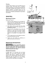
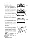
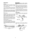
Locking the Spindle
1. Locate the spindle lock (F, Fig. 15) accessible
through the door on the right side of the
cabinet. Pull out and rotate 90º right or left,
resetting the knob into the indent.
Attempt to turn the spindle (B, Fig. 15) by hand
to verify that it is locked and will not rotate.
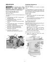
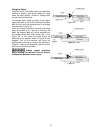
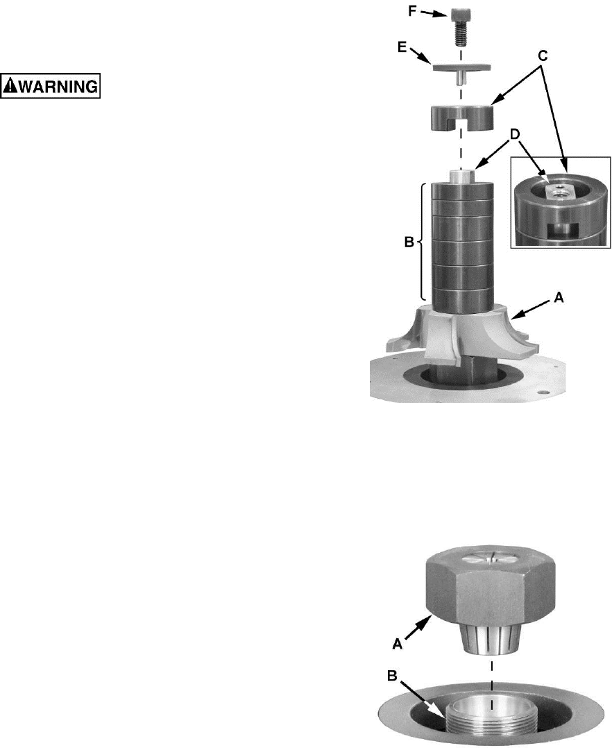
Installing the Shaper Cutter
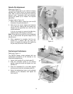
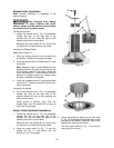
Referring to Figure 16:
1. Place the shaper cutter (A) (not included) onto
the spindle, oriented in the proper direction.
2. Place the spacers (B) and keyed collar (C) onto
the spindle.
Note: Spacers come in several widths and the
stacked selection (B) must be such that the top
of the keyed collar (C) sits slightly above the
top of the spindle (D). This will ensure sufficient
pressure to properly secure the shaper cutter
(A) when installation is complete.
3. Install the pronged washer (E) and socket head
cap screw (F). Tighten screw with the 8mm hex
wrench provided.
Unlocking the Spindle
4. Pull out the spindle lock (F, Fig. 15) accessible
through the door on the right side of the
cabinet. Rotate 90º right or left, resetting the
knob into the indent.
Using gloves to prevent injury from the
shaper cutter, turn the spindle (B) by hand to
verify that it turns freely.
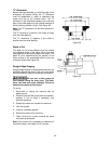
Router Collet (Optional) Installation
1. Locate the spindle lock (F, Fig. 15) accessible
through the door on the right side of the
cabinet. Pull out and rotate 90º right or left,
resetting the knob into the indent.
Attempt to turn the spindle (B, Fig. 15) by hand
to verify that it is locked and will not rotate.
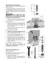
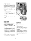
2. Place the router collet (A, Fig. 17) onto the
spindle (B, Fig. 17) and secure with the
wrench (K, Fig. 15) provided.
Figure 16
Figure 17
3. Unlock the spindle by pulling out the lock knob
(F, Fig. 15) accessible through the door on the
right side of the cabinet. Rotate 90º right or left,
resetting the knob into the indent.
Turn the router collet (A, Fig. 17) by hand to
verify that it turns freely.