


12
Coplanar Alignment
Follow steps 1–5 to determine if alignment is
necessary. Steps 6–9 will guide you through the
alignment if required.
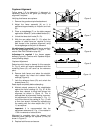
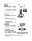
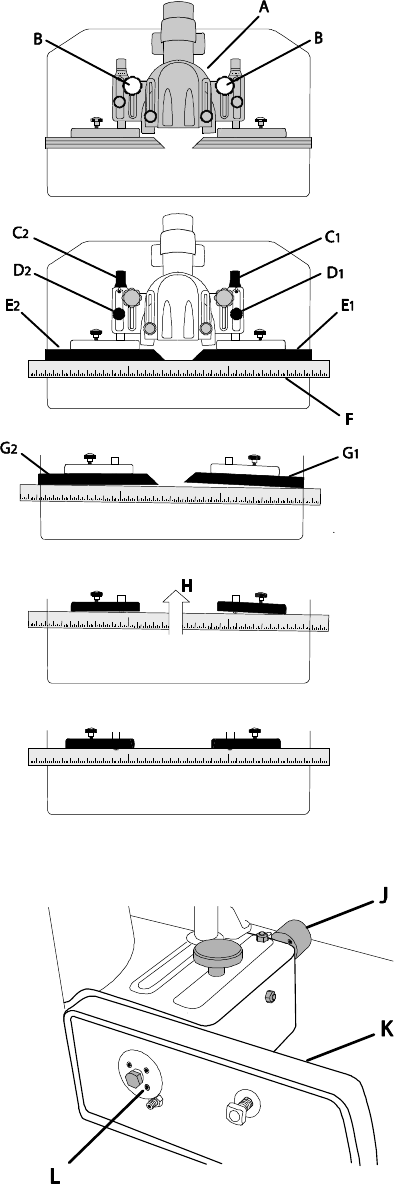
Verifying that fences are coplanar
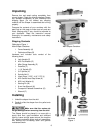
1. Remove the guard and spindle attachment.
2. Adjust the fence assembly (A) so it is
positioned approximately at midpoint and lock
(B).
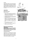
3. Place a straightedge (F) on the table pressed
against the infeed (E
1
) and outfeed fences (E
2
).
4. Unlock the fence lock knobs (D
1
, D
2
).
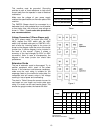
5. With the ram adjust dials (C
1
, C
2
) adjust the
position of either fence as required to bring
both fences in-line (coplanar alignment) using
the straightedge as the point of reference.
No adjustment is required if both fences are flush
with the straightedge as shown in Figure 7. Pro-
cede to Ram Dial Calibration (step 00).
Adjustment is required if the fences appear
skewed (Figure 8). Continue with Coplanar Adjust-
ment (following steps).
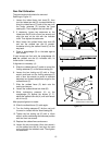
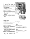
Coplanar Adjustment
Determine which fence is skewed (in this example:
G
1
, Fig. 8), which will require adjustment while the
remaining fence (G
2
) will serve as the reference
point.
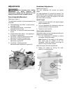
6. Remove both fences and place the straight-
edge against the infeed and outfeed fence
castings (Figure 9).
7. Lock the reference fence (D
2
) and unlock the
skewed fence (D
1
).
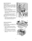
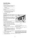
Read step 8 completely before attempting.
8. Maintain steady pressure of the straightedge
against the fence castings (H, Fig. 9). At the
same time, attempt to bring both fences into
alignment as shown in Figure 10. This is
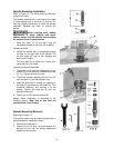
accomplished by alternately making incremen-
tal adjustments to four setscrews (L, Fig. 11)
on the front face of the casting (K, Fig. 11) with
a 2mm hex wrench, followed by repositioning
the casting with the micro adjust dial (J, Fig.
11) as required.
Important: It is recommended that the
adjustment setscrews (K, Fig. 11) be rotated in
1/16th increments or less at a time.
Alignment is complete when the skewed and
reference fence castings are coplanar (in-line) as
shown in Figure 10.
9. Replace both fences and secure.
Figure 6
Figure 7
Figure 8
Figure 9
Figure 10
Figure 11