


13
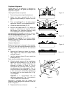
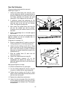
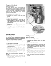
Ram Dial Calibration
The guard and spindle should be removed.
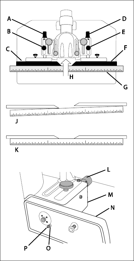
Referring to Figure 12:
1. Loosen the infeed fence lock knob (E), then
turn the infeed ram dial (D) counterclockwise to
bring the infeed fence (F) back all the way until
the limiter setscrew (P) touches the head
casting (M). Then retighten the lock knob (E).
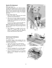
2. If necessary, loosen two setscrews on the
infeed ram dial (D) with a 2mm hex wrench and
align the zero on the dial with the indicator
mark. Then tighten the setscrews.
3. Next, loosen the outfeed fence lock knob (B)
and turn the outfeed ram dial (A) counter-
clockwise to bring the outfeed fence (C) all the
way back.
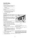
4. Place a straightedge (G) on the table against
both fences.
If both fences are flush with the straightedge (K)
and the outfeed ram dial (A) indicates zero, no
further action is necessary.
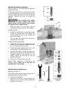
If alignment is necessary (J):
5. Slide the outfeed fence (C) aside to reveal the
limiting setscrew (P) on the fence casting (N).
6. Loosen the hex locking nut (O) with a 10mm
wrench and back out the limiting setscrew (P)
with a 3mm hex wrench to permit a sufficient
backward and forward adjustment range for the
outfeed fence (C).
7. Slide the outfeed fence (C) back onto the
casting and secure.
8. Loosen the outfeed fence lock knob (B).
9. While maintaining pressure (H) on the
straightedge (G) against the fences (C, F),
adjust the outfeed ram dial (A) until both fences
are in-line (K).
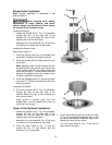
After proper alignment is made:
10. Slide the outfeed fence (C) aside again.
11. Turn the limiting setscrew (P) in (turn cw) until
it comes in contact with the head casting (M)
12. Tighten the hex locking nut (O) with a 10mm
wrench while maintaining the setscrew position
with the 3mm hex wrench.
13. Replace the outfeed fence and secure.
14. Loosen the two set-screws (2mm hex wrench)
on the outfeed ram dial (A) and align the zero
on the dial with the indicator mark. Then tighten
the setscrews.
-- Outfeed side is mirror image
Infeed side fence casting
Figure 12