


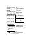
12
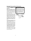
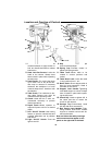
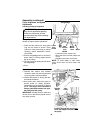
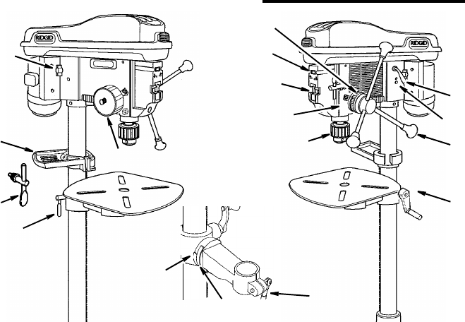
Location and Function of Controls
1. Belt Tension Handle...Turn handle
counterclockwise to apply tension to
belt, turn handle clockwise to release
belt tension.
2. Head Lock Set Screws...Locks the
head to the column. Always have
them locked in place while operating
the drill press.
3. Feed Handle...For moving the chuck
up or down. One or two of the han-
dles may be removed if necessary
whenever the workpiece is of such
unusual shape that it interferes with
the handles.
4. Table Crank...Turn clockwise to ele-
vate table. Support lock must be
released before operating crank.
5. Chuck...Holds drill bit or other rec-
ommended accessory to perform
desired operations.
6. Depth Scale...Allows operator to
adjust drill press to drill to a desired
depth.
7. Drill “On-Off” Switch...Has locking
feature to prevent unauthorized and
possible hazardous use by children
and others.
8. Light “On-Off” Switch...Turns the
light on and off.
9. Depth Scale Lock...Locks the depth
scale at selected depth.
10. Spring Cap...Provides means to
adjust quill spring tension.
11. Table Lock...Allows table to be
rotated in various positions and
locked.
12. Table Bevel Lock...Locks the table
in any position from 0°- 45°.
13. Bevel Scale...Shows degree table is
tilted for bevel operations. Scale is
mounted on side of arm.
14. Support Lock Handle...Tightening
locks table support to column. Always
have it locked in place while operat-
ing the drill press.
15. Chuck Key...Used to tighten drill in
the chuck and also to loosen the
chuck for drill removal.
16. Storage Tray...Conveniently holds
drill bits and other accessories.
17. Belt Tension Lock Handles...Tight-
ening handles locks motor bracket
support to maintain correct belt dis-
tance and tension.
Note and follow the safety warnings
and instructions that appear on the
panel on the right side of the head.
17
12
13
14
15
16
2
3
4
5
6
7
8
9
10
11
1