


25
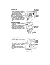
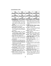
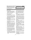
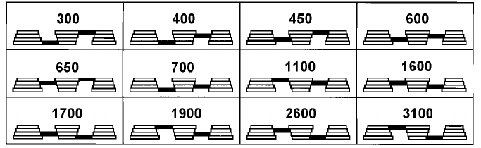
Spindle Speed in R.P.M.
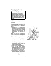
1. Drill Speed Table...Drill Speed can be
changed by placing the belt in any one
of the stepped pulleys. The spindle
speed chart, as shown above, lists
belt positions for the various spindle
speeds.
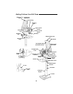
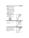
2. Belt Guard...Covers pulleys and belt
during operation of drill press.
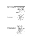
3. Belt Tension Lock Handle...Tighten-
ing handle locks motor bracket sup-
port to maintain correct belt distance
and tension.
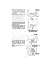
4. Belt Tension Handle...Turn handle
counterclockwise to apply tension to
belt, turn handle clockwise to release
belt tension. Refer to section “Assem-
bly-Installing and Tensioning Belt”.
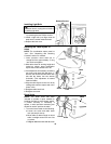
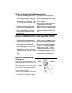
5. Head Lock Set Screws...Lock the
head to the column. Always have
them locked in place while operating
the drill press.
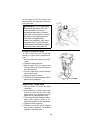
6. Feed Handle...For moving the chuck up
or down. One or two of the handles may
be removed if necessary whenever the
workpiece is of such unusual shape that
it interferes with the handles.
7. Column Collar... Holds the rack to the
column. Rack remains movable in col-
lar to permit table support movements.
8. Table Support...Travels up and down
on column. Supports arm and crank.
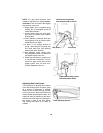
9. Table Crank...Turn clockwise to ele-
vate table. Support lock must be
released before operating crank.
10. Rack...Combines with gear mecha-
nism to provide easy elevation of table
by hand operated table crank.
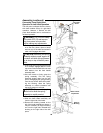
11.Base...Supports drill press. For addi-
tional stability, holes are provided in
base to bolt drill press to floor. (See
“Additional Safety Instructions for Drill
Presses”.
12. Column Support...Supports column,
guides rack, and provides mounting
holes for column to base.
13. Column...Connects head, table and
base on a one-piece tube for easy
alignment and movement.
14. Table...Provides working surface to
support workpiece.
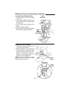
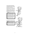
15. Depth Scale...Shows depth of hole
being drilled in inches and millimeters.
16. Depth Scale Indicator...Indicates
drilling depth selected on depth scale.
17. Depth Scale Lock...Locks the depth
scale to selected depth.
18. Spring Asm....Provides means to
adjust quill spring tension.
19. Belt Guard Latch...Press button to
raise belt guard.
20. Chuck...Holds drill bit or other recom-
mended accessory to perform desired
operations.
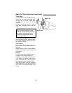
21. Arm...Extends beyond table support
for mounting aligning the table.
22. Table Bevel Lock...Locks the table in
any position from 0°- 45°.
23. Table Lock...Table can be rotated in
various positions and locked.
24. Bevel Scale...Shows degree table is
tilted for bevel operations. Scale is
mounted on table support, if it is to be
used for quick reference where accu-
racy is not critical.