


13
Assembly
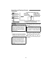
WARNING: To reduce the risk of
injury from unexpected starting or
electrical shock, never connect plug
to outlet until all assembly steps are
completed and you read and under-
stand all instructions.
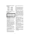
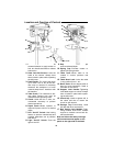
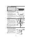
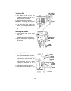
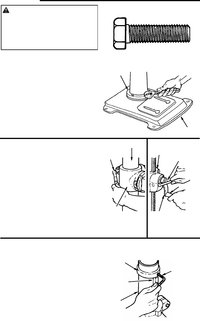
Assembly of Base/Column
1. Locate four (4) 10mm dia. x 40mm long
bolts among loose parts bag.
2. Position base on floor. Remove protec-
tive covering and discard.
3. Remove protective sleeve from column
tube and discard. Place column assem-
bly on base, and align holes in column
support with holes in base.
4. Install a bolt in each hole through col-
umn support and base and tighten with
adjustable wrench.
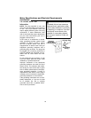
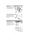
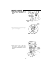
5. Locate table crank and support lock from
loose parts.
6. Install support lock from left side into
table support and tighten by hand.
7. Install table crank assembly and tighten
set screw with a 3mm hex “L” wrench.
Do not overtighten. Set screw should be
tightened against the flat section of the
shaft.
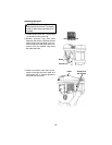
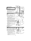
NOTE: To minimize crank backlash,
tighten support lock, rotate elevation
worm shaft clockwise, then assemble
crank tight against table support and
tighten set screw.
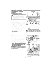
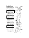
8. Check column collar for proper adjust-
ment. Collar should not be angled on the
column and it should be positioned so
rack will slide freely in collar when table
is rotated 360° around column tube. If
readjusted, only tighten set screw
enough to keep collar in place.
NOTE: To reduce the risk of column or
collar damage, do not overtighten set
screw.
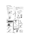
Base
10mm Dia. x 40mm
Hex Head Bolt (4)
Column
Support
Column
Support
Lock
Table
Support
Table
Support
Elevation
Worm Shaft
Handle
Table
Crank
Column
Collar
Rack
Column
Do Not
Overtighten
Set Screw