


21
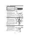
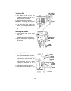
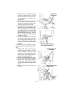
7. Remove the 4mm socket head cap
screw from the left side of the drill
press and install in the same position
on the right side of the drill press.
Tighten screw.
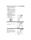
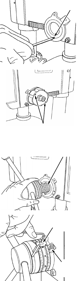
8. Remove the 6mm stop pin screw from
the right side of the drill press and
install in the left side of the drill press
as shown. Tighten stop pin screw.
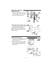
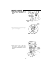
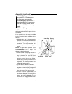
9. Install the feed handle assembly and
depth stop ring on the left side of the
drill press. With the chuck at its high-
est possible position, turn the depth
scale clockwise until it stops and
tighten the depth scale lock. This will
prevent the quill from dropping while
installing the spring.
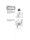
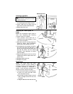
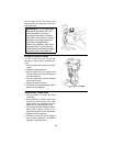
10. Install the spring assembly on the right
side of the drill press, making sure the
two housing screw heads face out-
wards. The center tab of the spring
must go in the slot on the feed handle
assembly.
If necessary, use a screwdriver to align
and keep spring centered during installa-
tion.
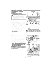
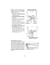
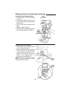
11. Replace M12 washer and screw the
outer and inner nuts back on the feed
handle assembly. Hold the spring
assembly in place and loosely assem-
ble both nuts. See following page for
quill return spring adjustment.
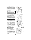
12. Remove the depth scale and reposi-
tion so numbers are legible as shown.
13. Remove the depth scale indicator
from the right side of the drill press
and reinstall on the left side of the drill
press.
14. Remove the scrap wood from the
table top.
Install 6mm
Stop Screw
Right side housing screws
face outward as shown
Install Feed Handle
Assembly
Remove Depth Scale
and Reposition
Install Depth
Scale
Indicator