Page 16
ASSEMBLY
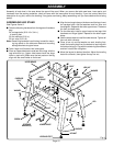
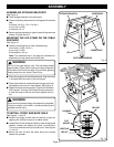
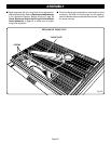
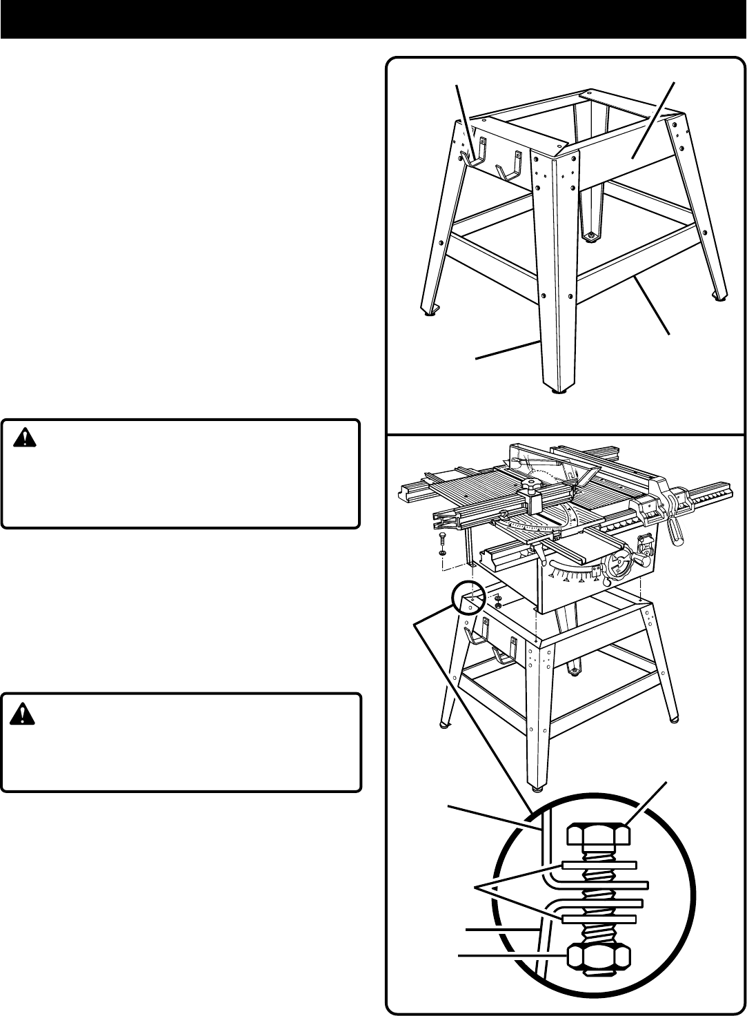
ASSEMBLING STORAGE BRACKETS
See Figure 9.
■ Take storage brackets from loose parts.
■ Take the following hardware from the leg stand hardware
bag:
4 screws (1/4-20 x 1/2 in. Pan Hd.)
4 hex nuts (1/4-20)
4 washers (1/4 in.)
■ Secure storage brackets to upper braces of leg stand as
shown in figures 8 and 9.
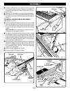
MOUNTING THE LEG STAND ON THE TABLE
SAW BASE
See Figure 10.
■ Take the following from a small hardware bag:
4 hex bolts (1/4-20 x 3/4 in.)
4 hex nuts (1/4-20)
8 flat washers (1/4 in.)
Note: This hardware was in the bag with hardware for
assembling the leg stand and leveling feet.
WARNING:
Do not lift the saw without help. The saw base weighs
approximately 75 lbs. Hold it close to your body. Keep your
knees bent and lift with your legs, not your back. Ignoring
these precautions can result in back injury.
■ Place the leg stand on the table saw base. Align the holes
in the table with the holes in the end braces.
■ Place a flat washer on a bolt and insert through hole. Add
a flat washer and a hex nut. Hand tighten.
See Figure 10.
■ Repeat for three remaining holes. Tighten all hardware
with a wrench. You may find it helpful to use one wrench
to hold the head of the bolt and one to tighten the hex
nut.
WARNING:
Do not connect to power supply until assembly is complete.
Failure to comply could result in accidental starting and
possible serious injury.
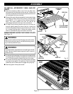
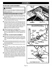
TO INSTALL FRONT AND BACK RAILS
See Figures 11 and 12.
■ Position end plugs on both rails and secure in place by
tapping with a block of wood or a rubber mallet.
■ Loosen the front rail clamps one half turn from the tightened
position. Loosen the square rail holder nut one-fourth
(1/4) turn to allow the front rail to slide over it.
See Figures
11 and 12.
■ Mount the front rail with the scale facing the outside
toward the operator.
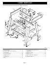
LEG STAND ASSEMBLED
LEG
LOWER BRACE
UPPER BRACE
STORAGE BRACKET(S)
Fig. 9
Fig. 10
HEX BOLT
HEX NUT
FLAT
WASHER
SAW BASE
LEG STAND


