


Page 38
L
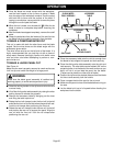
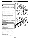
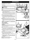
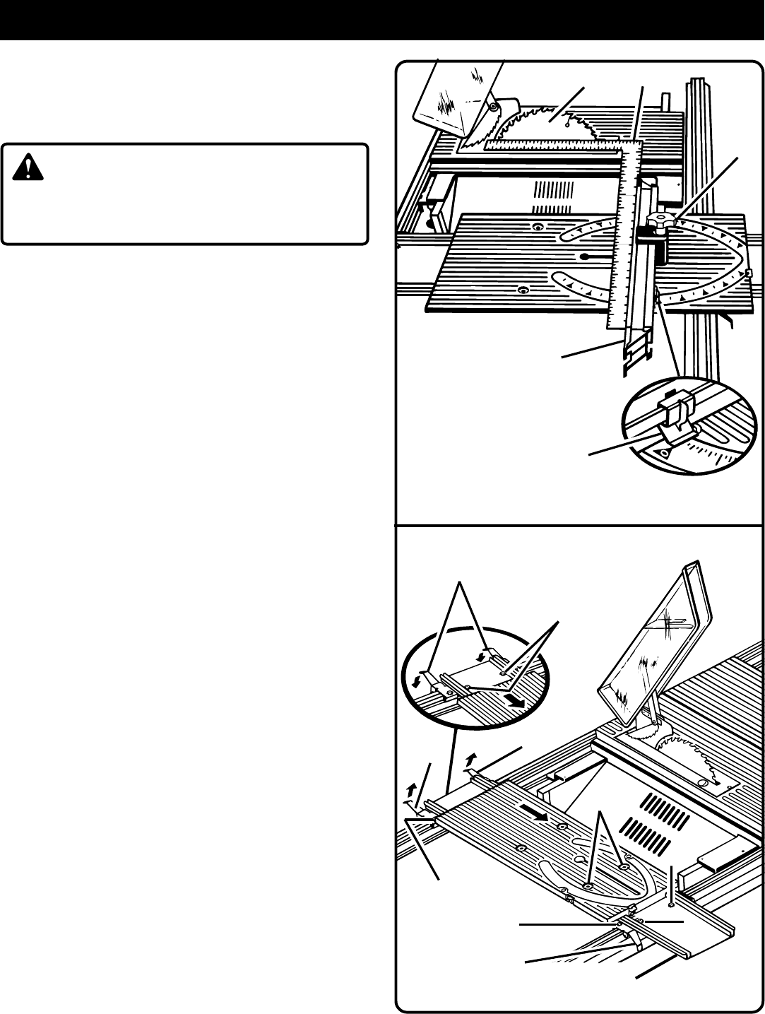
To Check Miter Fence Alignment
See Figure 53.
The miter fence must be perpendicular to the blade when set
at zero degrees.
WARNING:
Begin by unplugging your saw. Failure to unplug saw
could result in accidental starting causing possible serious
injury.
■ Set the miter fence (H) at 0° as shown in figure 53. Miter
indicator (I) should be set precisely on 0° and secured in
place with adjusting clamp (J).
Note: The quick-stop is not necessary for this checking
procedure. However, you may want to check and adjust
it to 0° at this time. See
Quick-Stop
section that follows.
■ Place a framing square (G) firmly against the miter fence
(H) with the other side against the blade (E).
■ Check whether the miter fence and blade are square with
each other. With the framing square against the miter
fence there should be no gap from the front to the rear of
the blade.
■ If a gap exists, the miter fence may be out of square.
■ Rotate the blade and recheck. If there is a consistent gap
between the front and rear of the blade, the miter table
needs aligning. Follow the adjustment procedures that
follow.
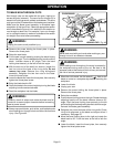
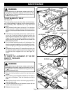
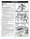
MAKING ADJUSTMENTS TO SLIDING MITER
TABLE ASSEMBLY
To Adjust the Miter Base
See Figure 54.
REMEMBER: Check all settings before loosening screws for
the following procedures. Once screws have been loosened,
these settings must be reset.
Eight screws are visible on the miter base (B).
■ Four screws (K) are on the holder plates and secure these
plates to the rails. It is not necessary to loosen or adjust
these screws for this adjustment procedure.
■ Another pair of screws (L) is in the base, at the rear.
Loosen these two screws (L) and the rear miter locking
clamps (M).
■ The last pair of screws is located on the infeed side of the
base. Loosen the left screw (N) only.
■ The right screw (O) will be used as a pivot point.
Note: The front two miter locking clamps (P) and rail
clamps should remain locked.
■ Follow the steps in TO CHECK MITER BASE
PARALLELISM, adjust the miter base so that it is parallel
to the blade.
■ Retighten the left front screw (N).
■ Clamp the rear miter locking clamps (M).
■ Retighten the two rear screws (L).
H
I
J
G
E
Fig. 53
Fig. 54
M
R
P
K
M
M
B
N
O
K
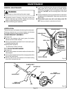
MAINTENANCE