


Page 17
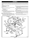
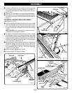
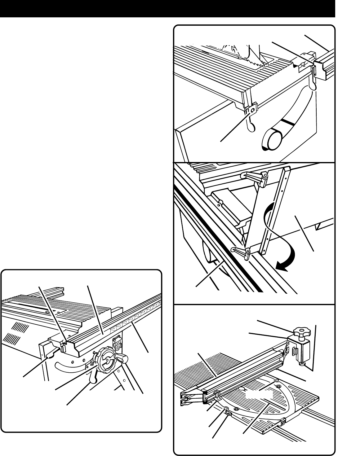
Fig. 12
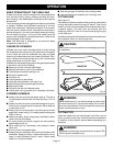
Fig. 11
RAIL
HOLDER NUT
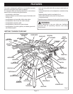
■ Check to make sure the rail clamps will securely clamp
the rail before sliding the entire assembly into position. If
not, tighten the square rail holder nut one-fourth (1/4) turn
and recheck.
■ Slide the rail into position over both clamps and secure.
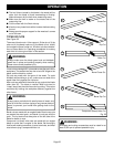
■ Mount the rear rail, following the same clamping procedure
as shown for the front rail. Orient the rear rail as shown in
Figure 12.
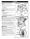
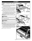
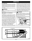
TO INSTALL MITER TABLE AND FENCE
See Figures13 and 14.
■ Install the sliding miter table assembly over the front and
rear rails.
See Figure 13.
Check that it slides easily on the
rails. Push both front miter locking clamps down evenly
on each side to secure. Repeat for both rear miter locking
clamps.
Note: DO NOT force miter locking clamps fully down.
Tighten only to flat "seated" position.
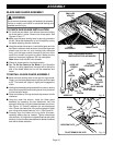
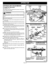
■ To install the miter fence holder to the miter fence, loosen
the attachment bolt by turning the adjusting clamp (the
knob on top) counterclockwise. Make sure the adjusting
clamp is loose enough so the bolt has enough clearance
to slide in the table slot. Slide the tabs into the grooves
in the miter fence.
See Figure 14.
■ Mount the miter fence to the miter table by installing the
locator pin (below the miter fence) into hole “A” or “B”.
(Hole "A" is closest to the blade.) At the same time, place
the attachment bolt in the slot. Secure the adjusting
clamp, but do not tighten.
■ Adjust the miter indicator to the scale.
■ Securely tighten the adjusting clamp.
ASSEMBLY
REAR RAIL
MITER
TABLE BASE
REAR RAIL
Fig. 13
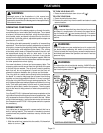
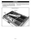
END PLUG
SCALE
BEVEL
LOCKING LEVER
END PLUG
FRONT RAIL
HANDWHEEL
BLADE
ADJUSTING
HANDLE
FRONT
RAIL CLAMP
LOCATOR
PIN
ADJUSTING
CLAMP
MITER
FENCE HOLDER
MITER FENCE
MITER
INDICATOR
HOLE "B"
TABLE
SLOT
ATTACHMENT
BOLT
HOLE "A"
Fig. 14
QUICK
STOP