


Page 18
Fig. 15
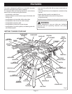
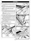
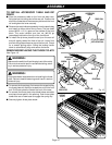
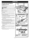
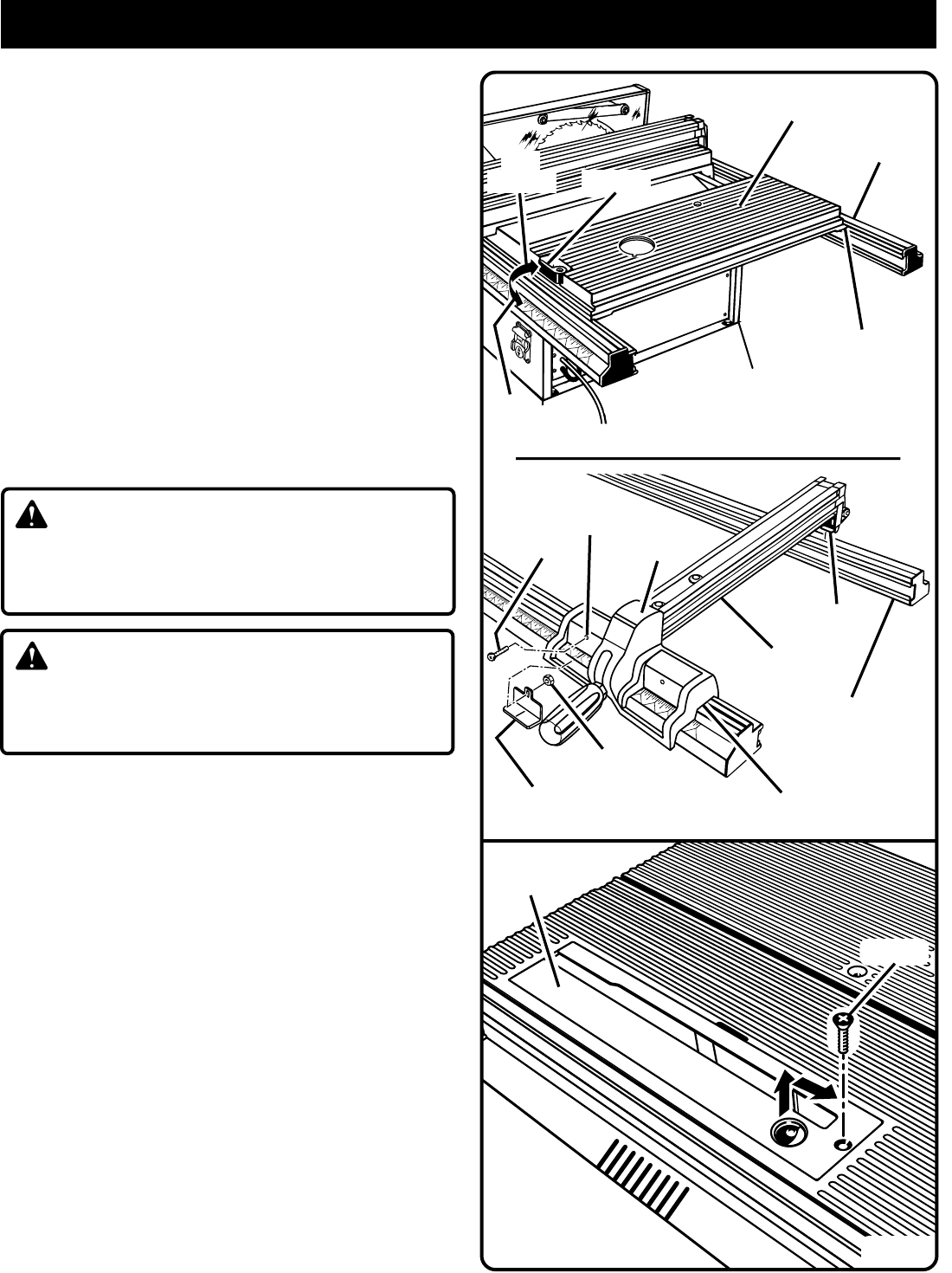
TO INSTALL ACCESSORY TABLE AND RIP
FENCE
■ Place the accessory table on the front and back rails,
fitting the lips into the top slot of the rear rail. Position the
slot on the underside of the accessory table onto the front
rail and tighten the lever securely.
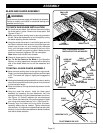
■ Remove the scale indicator assembly from the plastic bag
and install on either side of the rip fence. The pan head
screw (#8-32 x 1/2 in.) goes on the outside of the front
block. The scale indicator and hex nut (#8-32) go
immediately behind the front lip of the front block.
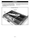
■ To install the rip fence, place the rear lip on the rear rail
and pull slightly toward the front of the unit. Lower front
end onto the guide surfaces on top of the front rail. Check
for a smooth gliding action. Swing the locking handle
down to automatically align and secure the fence.
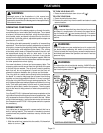
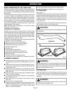
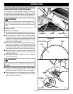
REMOVING/REPLACING THE THROAT PLATE
See Figure 16.
WARNING:
Make sure the switch is off and the plug is out of the outlet.
Failure to do so could result in accidental starting, result-
ing in serious personal injury.
WARNING:
Drop blade below saw table when reinstalling the throat
plate. Failure to heed this warning could result in serious
personal injury.
■ To remove the throat plate, first remove the screw holding
the throat plate with a phillips screwdriver and lift the front
end. Pull throat plate out toward the front of the saw.
■ To reinstall the throat plate, drop blade below saw table
and place throat plate in the opening. Push throat plate
toward the rear of saw base to engage the spring clip.
■ Securely tighten throat plate screw.
ASSEMBLY
SCREW
FRONT
BLOCK
MOUNTING
HOLE
RIP FENCE
HEX NUT
SCALE
INDICATOR
FRONT LIP
REAR LIP
REAR RAIL
ACCESSORY
TABLE
REAR RAIL
FIT LIP OF TABLE
INTO REAR RAIL
LEVER
THROAT
PLATE
SCREW
Fig. 16
TO
LOCK
TO
UNLOCK