


Page 36
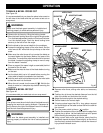
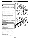
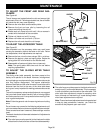
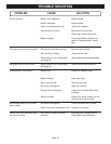
TO ADJUST THE FRONT AND REAR RAIL
CLAMPS
See Figure 49.
The rail clamps are located below the rails and ensure tight
attachment of the rail. Following extended use, the rail holder
nut inside the rails may need adjusting.
■ Remove the miter table and accessory table.
■ Remove the front and rear rails by loosening the rail
clamps and sliding the rails off.
■ Rotate each rail clamp to the left until it hits or comes in
contact with the bottom of the saw table.
■ Tighten rail holder nut until it is snug.
■ Loosen rail holder nut one-fourth (1/4) turn.
■ Replace the rails and check the rail clamps.
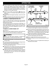
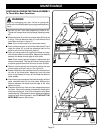
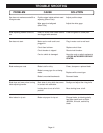
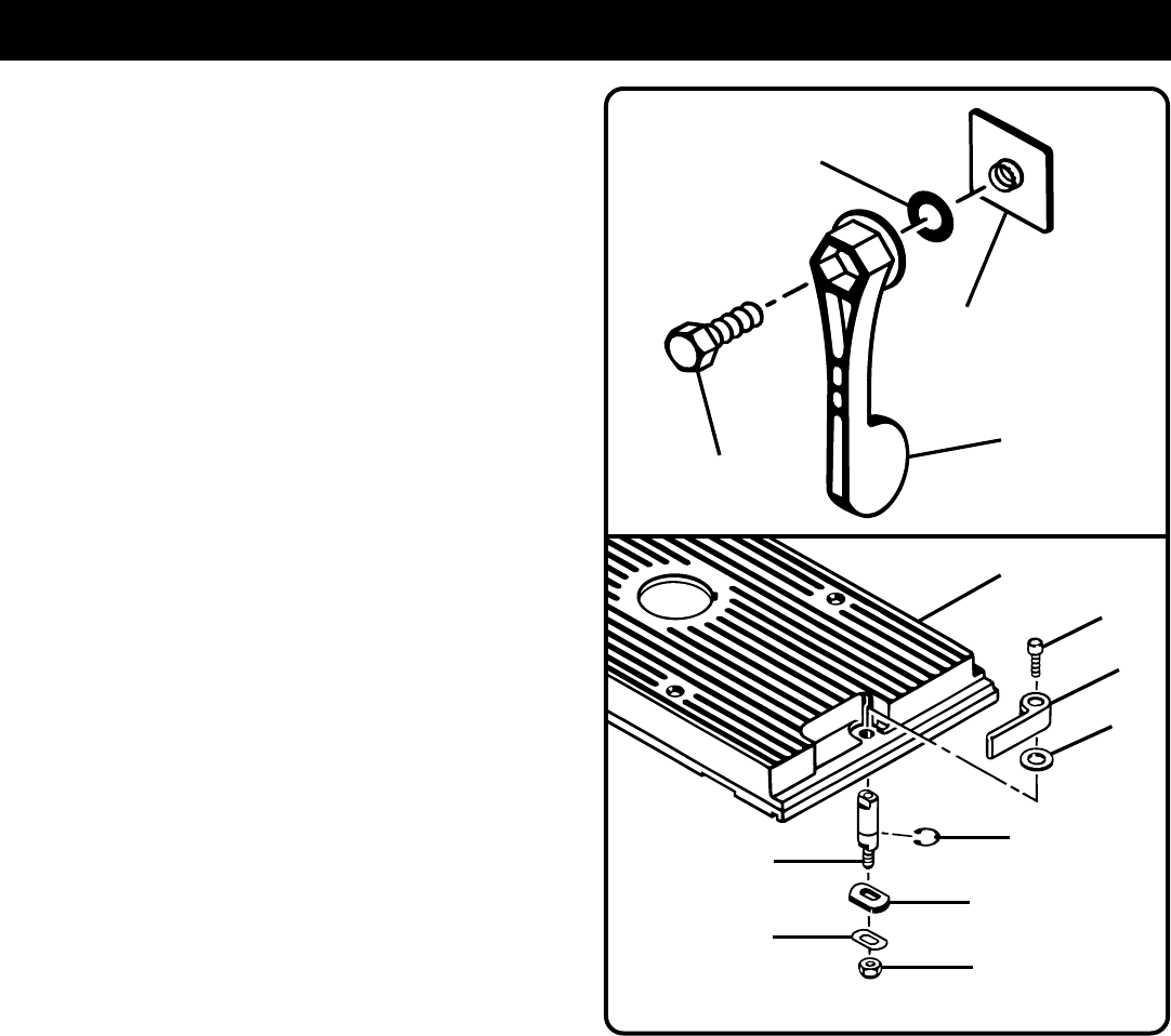
TO ADJUST THE ACCESSORY TABLE
See Figure 50.
After extended use, the accessory table may work loose
causing the accessory table to be loose on the rails. Follow
the steps below, when adjustments are required:
■ Remove the hex nut on the lever using a 3/8 in. nut driver.
■ Remove the backup plate and spring plate. Rotate the
spring plate 180° and reinstall on the handle shaft.
■ Reassemble all parts and tighten hex nut securely.
Note: The spring plate offers two ends for use before
requiring replacement.
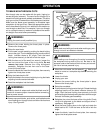
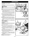
TO ADJUST THE SLIDING MITER TABLE
ASSEMBLY
The sliding miter table assembly has been preset at the
factory to be parallel to the blade. However, misalignment
during shipping or requirements for very precise and accurate
cuts may require realignment. The square relationship
between the blade and the miter fence as it travels the entire
distance from the front to the rear of the miter table base
during a cut is very important for making precise and accurate
cuts.
To avoid unnecessary setups and adjustments, we suggest
that you check these setups carefully with a framing square
and make practice cuts in scrap wood before making finish
cuts in good workpieces.
Note: Follow the general rule of measuring twice and cutting
once.
Do not loosen any screws for the following adjustments until
you have made checks and are sure adjustments are needed.
Once screws have been loosened, these settings must be
reset.
Two basic checks should be made to determine if adjustments
are necessary:
■ The miter base must be parallel to the blade as the table
slides from the front to the rear of the miter table assembly.
WASHER
RAIL
CLAMP
RAIL
HOLDER NUT
HEX
MOUNTING BOLT
Fig. 49
RETAINING
RING
ACCESSORY TABLE
CAP SCREW
LEVER
BACKUP
PLATE
HANDLE
SHAFT
Fig. 50
HEX NUT
SPRING PLATE
WASHER
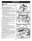
■ The miter fence must be square to the blade when set at
exactly zero (0°) on the miter table scale. This is necessary
in order to be able to use the scale on the miter table. The
miter table has adjustment screws for squaring miter
fence to blade and maintaining 0° scale settings when
miter base adjustments are required.
Note: These checks and adjustments are being explained
in step by step procedures, however, you should be
aware that they depend upon each other.
MAINTENANCE