


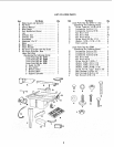
5. Fromamongthelooseparts,find thefollowing
hardware:
4 CarriageBolts,5/16- 18×3/4in,long
4 Flatwashers17/64x 3/4x 1/16
4 Hex.Nuts,5/16- 18(approx,dia.of ho_e5/16
in.)
4 Lockwashers.5/16in. ExternalType
(approx.alia.of hole5/t6 n.)
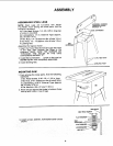
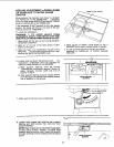
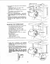
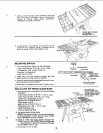
6. #lacemotoronMOTORMOUNT... insertbolts
throughholesinMOUNTthenthroughthemotor.
Install Iockwashers.and hex. nuts. Do not
tighten.
7. PositionMOTORBASEon MOTORMOUNTso
theedgesofthe MOTORBASEandtheMOTOR
MOUNTare even. Tighten all 4 Hex. nuts
securely.
THESE TWO EDGES_EVEN __
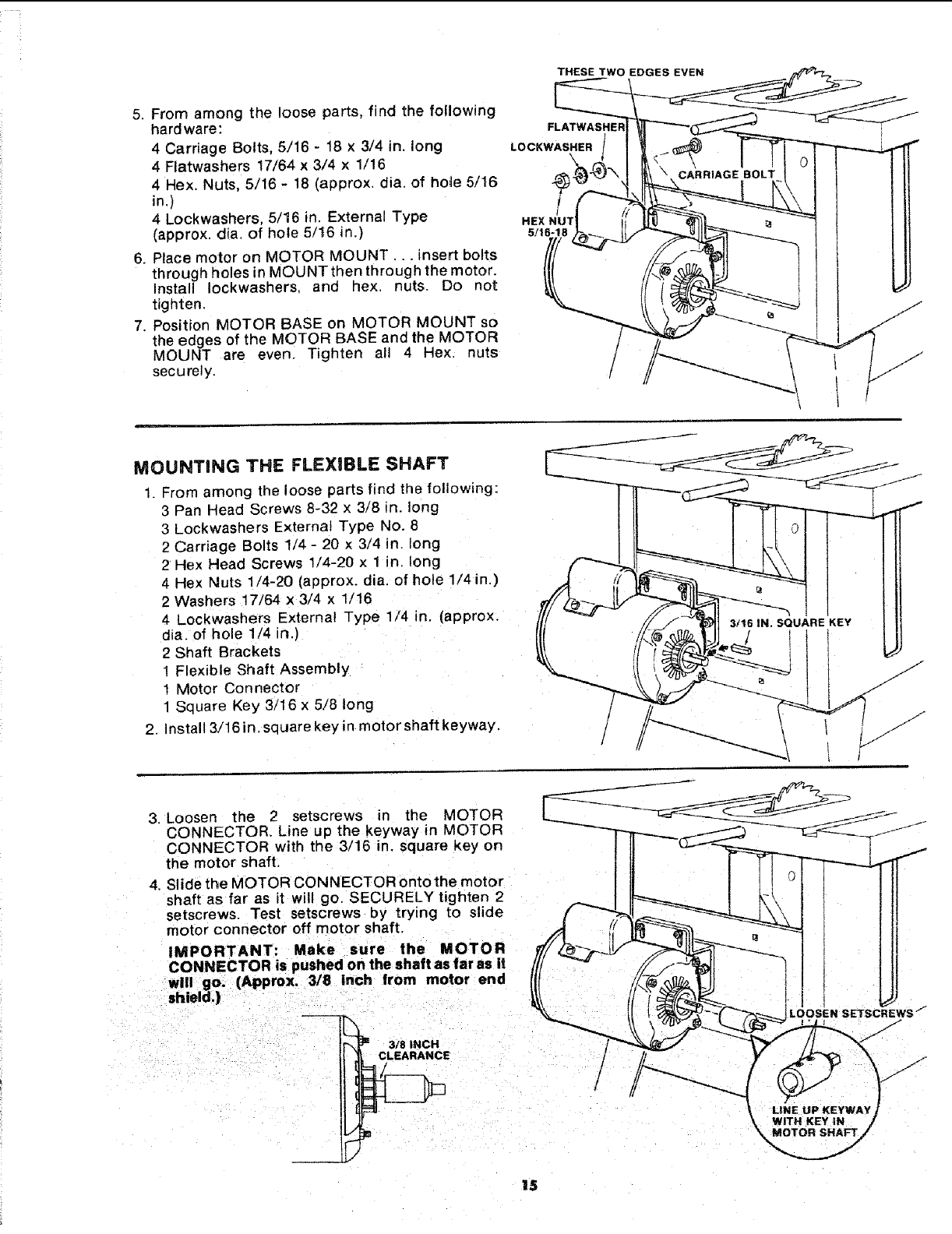
MOUNTING THE FLEXIBLE SHAFT
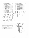
1. From among the loose parts find the following:
3 Pan Head Screws 8-32 x 3/8 in. long
3 Lockwashers Externat Type No. 8
2 Carriage Bolts 1/4 - 20 x 3/4 in. long
2 Hex Head Screws 1/4-20 × 1 in. long
4 Hex Nuts 1/4-20 (approx. dia. of hole 1/4 in.)
2 Washers 17/64 x 3/4 x 1/16
4 Lockwashers External Type 1/4 in. (approx.
alia. of hole 1/4 in.)
2 Shaft Brackets
1 Flexible Shaft Assembly
1 Motor Connector
1 Square Key 3/16 x 5/8 long
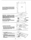
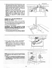
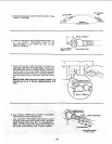
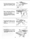
2. Install 3/16 in. square key in motor shaft keyway.
Loose.t.o2setscrews.he.OTO.
3. CONNECTOR. Line up the keyway in MOTOR _-_-_-nr_.___ j i_f
CONNECTOR with the 3/16 in. square key on i tl £z"'I--"_---_----_ i J
t.e o,or Ill
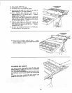
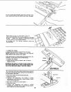
4. SlidetheMOTOROONNECTORontothemotor II! I t! °l ! I1t
shaft as far as it will go. SECURELY tighten 2 __ I I_-------_ I k-\ I { I It
setscrews. Test setscrews by trying to slide f _'_l..=..__----------_t \\ I I I II
motor connector off motor shaft. /_ _/ _-"_ _ t !li
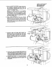
CONNIECTOR is puslted on the shaft as far as it /1/ ""_,_¢ _ _f-_! --71i I!l
_._,,So.€,pp,o=_8,.o,,,oretoo,o,..,
IL_ = 3/8 INCH
_5