


-12-
W1668 13
1
⁄4" Oscillating Drill Press
SETUP
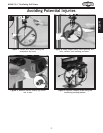
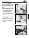
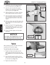
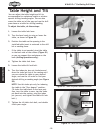
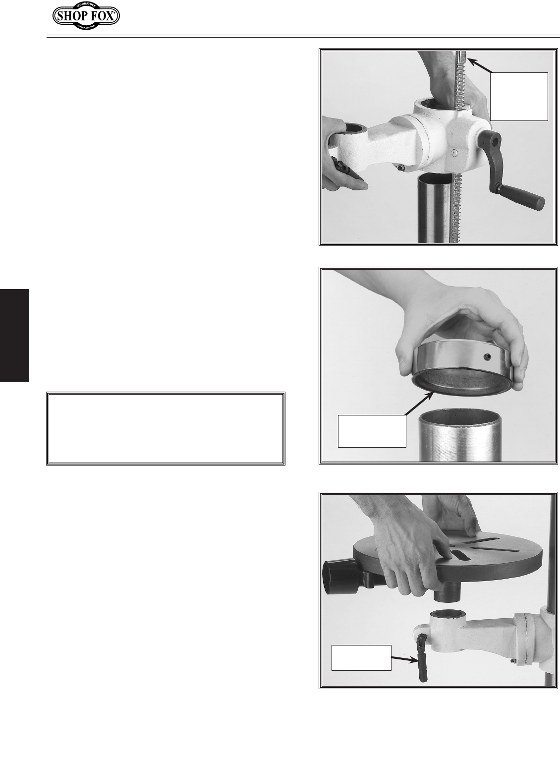
Figure 13. Rack, column, table support position.
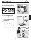
Figure 14. Column ring bevel positioning.
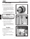
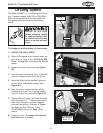
Figure 15. Table installation.
6. Position the rack so the long un-toothed
end is facing upward (see Figure 13).
7. Insert the rack into the table support
bracket so the teeth face out and mesh
with the pinion (see Figure 13).
8. While holding the rack in place, slide the
table support bracket onto the column.
9. Allow the bracket and rack to slide down
until the bottom of the rack bevel slips
into the tapered shoulder on the column
support.
10. Slide the column ring onto the column with
the inside bevel in the down position (see
Figure 14).
11. Adjust the ring until the tip of the rack
fits inside the bevel, and
the rack rotates
freely when you rotate the table support
around the column.
12. Secure the table support with the table
lock lever.
Column Ring
Bevel Facing
Downward
10mm Lock
Handle
Long
Un-toothed
Rack End is
Facing
Upward
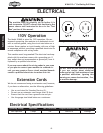
Use caution when tightening the set screw.
Over tightening will split the column ring.
NOTICE
When installed correctly, the table should lock
in position with firm lever torque.
To install the table, do these steps:
1. Thread the 10mm lock handle into the
table bracket through the blind hole, into
the threaded hole, and thread inward three
turns.
2. Align the shaft under the table with the
hole on the end of the table support brack-
et and install (see Figure 15).
3. Tighten the table lock lever.
Ta bl e
13. Carefully tighten the set screw on the ring.