


-37-
N(/(*(/Fg\e<e[N`[\9\ckJXe[\i
J<IM@:<
I\gcXZ`e^:fem\pfi 9\ck
If the conveyor belt becomes damaged or too worn to prop-
erly adjust the tension, you must replace it.
KffcjE\\[\[ Hkp
Hex Wrench 4mm ...............................................1
Hex Wrench 5mm ...............................................1
Wrench 10mm ...................................................1
Wrench 12mm ...................................................1
Kfi\gcXZ\k_\Zfem\pfiY\ck#[fk_\j\jk\gj1
(% DISCONNECT THE SANDER FROM POWER!
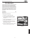
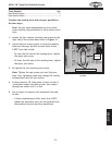
)% Remove the cap screws and flat washers securing
the front and rear conveyor roller guards (see =`^li\
*-), then remove the guards.
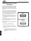
*% Loosen the conveyor tension jam nuts on either side
of the conveyor (see =`^li\*.), then release the
tension on the conveyor belt by loosening the ten-
sion adjustment bolts.
+% Remove the three cap screws securing the c\]k front
roller bracket shown in =`^li\*., then, while sup-
porting the front conveyor roller assembly with one
hand, remove the bracket.
,% Carefully pull the front conveyor roller assembly
from the conveyor belt.
Note: 8kk_`jgf`ek#k_\]ifekifcc\iYiXZb\k`jjk`cc
XkkXZ_\[kfk_\Zfem\pfifek_\i`^_kj`[\Xe[n`cc
jkXp`egcXZ\%
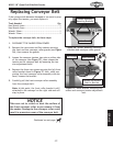
=`^li\*-% Sander assembly mounting
brackets and conveyor roller guards.
Roller Guards
Sander Assembly
Mounting Brackets
=`^li\*.% Roller bracket mounting cap
screws and conveyor tension adjustment
bolt.
Tension Adjustment
Bolt & Jam Nut
Cap Screws
Roller Bracket
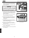
NOTICE
Take care not to scratch or dent the surface of
the front conveyor roller as you remove it from
the sander. Damage to the conveyor roller could
result in premature wear of the conveyor belt.
Continued on next page