


-36-
For Machines Mfg. Since 8/11
Model SB1001 8K
™
Lathe
OPERATION
2. Rotate the rest to the desired angle, as
indicated by the scale at the base, then re-
tighten the two hex nuts.
Tip: If setting up to cut external right-hand inch
or metric threads, or internal left-hand
threads for the first time, set the compound
rest so its travel is perfectly parallel with the
cross slide. Then, using a protractor, rotate
the compound 29.5° counterclockwise and
mark the new location on the cross slide.
This mark will be the quick reference point
for setting the offset angle. To mark for
internal right-hand threads or external left-
hand threads, repeat this process, but rotate
the rest 29.5° clockwise and mark the cross
slide accordingly.
The compound rest ball handle has an indirect-
read graduated scale. This means that the
distance shown on the scale represents the actual
distance the cutting tool moves. The base of the
compound rest has another graduated scale used
for setting the cutting tool to a specific angle.
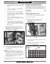
Graduated Dial
Increments .....................................................0.001"
One Full Revolution ......................................0.050"
Tool Needed for Adjusting Angle Qty
Wrench 14mm .......................................................1
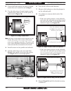
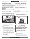
To set the compound rest at a certain angle:
1. Loosen the two hex nuts at the base of the
compound rest (1 of 2 shown in Figure 41).
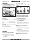
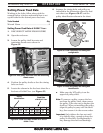
Compound Rest
Figure 41. Compound rest.
Compound
Rest
Hex Nut
(1 of 2)
Angle Scale
The four-way tool post is mounted on top of the
compound rest and allows a maximum of four
tools to be loaded simultaneously.
Each tool can be quickly indexed to the workpiece
by loosening the top handle, rotating the tool
post to the desired position, then re-tightening
the handle to lock the tool into position.
Installing Tool
Tool Needed Qty
Hex Wrench 6mm .................................................1
To install a tool in the tool post:
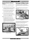
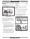
1. Adjust the tool post cap screws so that the
cutting tool can fit underneath them (see
Figure 42 for an example).
Four-Way Tool Post
2. Firmly secure the cutting tool with at least
two tool post cap screws.
3. Check and adjust the cutting tool to the
spindle centerline, as instructed in the next
subsection.
Over-extending a cutting tool from the post
will increase the risk of tool chatter, breakage,
or tool loosening during operation, which
could cause metal pieces to be thrown at
the operator or bystanders with great force.
DO NOT extend a cutting tool more than
2.5 times the width of its cross-section
(e.g, 2.5 x 0.5" = 1.25").
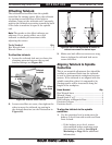
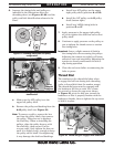
Figure 42. Example of tool mounted in tool post.
Cutting
Tool
Tool Post
Bolt