


For Machines Mfg. Since 8/11 Model SB1001 8K
™
Lathe
-43-
OPERATION
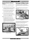
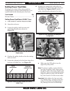
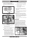
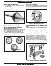
6. Arrange the timing belts and pulleys as
indicated in the illustration above the
threading chart (see Figures 61–62) and the
pulley and belt identification column in the
chart.
Figure 61. Threading timing belt and pulley
configuration.
F
16
A
B
D
E
a. Make sure the 16T pulley is on the
upper left pulley shaft.
b. Remove the pulley and bushing from the
A–B pulley shaft (see Figure 62).
Note: To remove a pulley, remove the hex
nut from the pulley shaft, then remove
the pulley. Take care not to displace
the shaft key. When re-installing the
pulleys, align the pulley keyway with
the shaft key, then secure it in the
reverse order. Only tighten the hex nut
until it is slightly snug—enough to keep
the pulley on the shaft. Overtightening
it may damage the shaft and bushings.
c. Install two 48T pulleys on the upper
right pulley shaft (positions A and B).
d. Install the 18T pulley on the D pulley
shaft (bottom right).
e. Install two 140XL timing belts in
positions E and F.
7. Apply pressure to the upper right pulley
as you re-tighten the shaft hex nut on that
pulley shaft.
8. Continue to apply pressure on the pulley as
you re-tighten the thumb screw to tension
the timing belts.
Important: Leave a slight amount of slack in
the timing belts when securing the pulleys.
Adjusting the tension too tightly will cause
excessive wear and stretching. Adjusting the
tension too loosely could cause the belt to
slip during operation.
9. Close the end cover before re-connecting the
lathe to power.
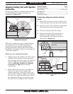
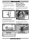
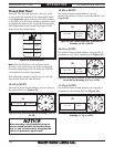
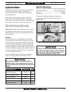
Thread Dial
The numbers on the thread dial show when
to engage the half nut during inch threading
(refer to thread dial chart for number usage).
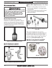
The thread dial gear must be engaged with
the leadscrew for this to work. Use a 5mm
hex wrench to loosen the cap screw shown
in Figure 63, pivot the dial gear toward the
leadscrew so that it properly meshes with the
leadscrew threads, then re-tighten the cap screw
to hold it in place.
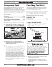
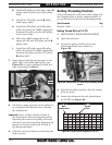
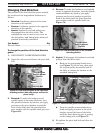
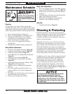
Figure 62. Threading timing belt and pulley
identification.
Pulley
Removed
From Here
A & B-48T
Pulleys
F-140 Belt
D-18T Pulley
E-140 Belt
16T
Pulley
Figure 63. Thread dial gear engaged with leadscrew.
Cap
Screw
Dial
Gear