


-16-
For Machines Mfg. Since 7/09
EVS Toolroom Lathes
PREPARATION
Connecting Power Cord to Lathe
Electrocution or death will occur if you
attempt this procedure with the power cord
connected to the power source. The cord
must be disconnected from power before
performing this procedure.
These instructions are for setups where the lathe
will be connected to the power source with a
power cord and plug, as opposed to a hardwire
setup.
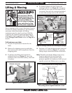
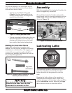
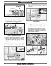
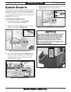
To connect power cord to the lathe:
1. Unlock and open the main electrical cabinet
door, and install a strain relief in the
location shown in Figure 14.
Figure 14. Location to connect power inside main
electrical cabinet.
Incoming
Power
Strain
Relief
Main
Power
Switch
4. Make sure the cord/wires have loose slack
between the strain relief and terminal
connections, then tighten the strain relief to
secure the power cord.
Note: The strain relief must be tightened against
the outermost jacket of the cord. Avoid over-
tightening the strain relief or it may crush
the cord and cause a short.
5. Test the strain relief to ensure it is properly
tightened by pulling the cord from outside
the box with light-to-moderate force. When
the strain relief is properly tightened, the
cord will not slide.
6. Close and lock the main electrical box door.
2. Thread the power cord through the strain
relief, and up to the main power switch
shown in Figure 14.
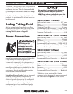
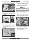
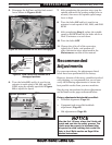
3. Connect the incoming L1, L2, L3 and ground
wires to the main power switch terminals, as
illustrated in Figure 15.
To Power Source
L3
L3
L1
L1
L3
L2
L1
Gn
G
G
G
G
G
G
G
G
G
G
G
G
G
n
t
Wt
W
t
Rd
Rd
Ground
1
1
1
2
3
3
3
5
5
5
6
4
MASTER
POWER SWITCH
L2
L2
Bk
B
Figure 15. Power connection at main power switch.
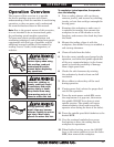
Hardwire setups require power supply lines to
be enclosed inside of conduit, which is securely
mounted and constructed in adherence to
applicable electrical codes.
A hardwire setup for this machine must be
equipped with a locking disconnect switch
as a means to disconnect the power during
adjustments or maintenance, which is a typical
requirement for lock-out/tag-out safety programs
(commonly required by OSHA).
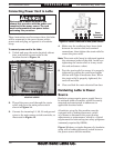
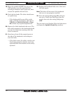
Figure 16 shows a simple diagram of a hardwire
setup with a locking disconnect switch between
the power source and the machine.
Power
Connection
Terminals
Hardwiring Lathe to Power
Source