


-70-
For Machines Mfg. Since 7/09
EVS Toolroom Lathes
SERVICE
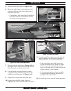
5. Remove pedal stop shown in Figure 139.
6. Move the brake band to the right one hole,
and re-install the pedal stop, tightening it
until it is just snug.
— If installing a new brake band, install the
cap screw so there is one hole to the left
for future brake adjustment.
7. Firmly push the pedal lever (Figure 140) to
the right until it stops and the brake band is
fully clamped around the brake hub.
8. Tap the pedal stop into position so there
is approximately a 25mm gap between the
pedal lever and the stop (see Figure 140).
9. Tighten the cap screw on the pedal stop.
10. Locate the motor kill switch (shown in
Figure 141) at the tailstock end of the lathe.
11. Push the pedal lever down to verify that the
cam lobe pushes the kill switch plunger in.
When pushed in, the switch should click.
— If the switch does not click, loosen the
switch mounting screws, push the pedal
all the way down, and move the switch
closer to the lobe until it clicks. Secure the
switch in place at this location.
— In the released position, there should be
an approximate 3mm gap between the
plunger roller and the lobe.
12. Re-install the cover, test the brake operation.
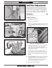
Figure 139. Brake linkage adjustments.
Move Pedal Stop Left or Right to
Adjust Foot Pedal Height.
Move Brake Band to the
Right to Adjust Brake
Pedal Stop
Pedal Lever
Cap Screw
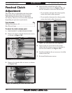
Plunger
and
Cam Lobe
Motor Kill
Switch
Figure 141. Motor kill switch.
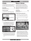
Figure 140. Pedal travel adjustment.
25mm
Pedal
Lever
Pedal Stop