


For Machines Mfg. Since 7/09 EVS Toolroom Lathes
-29-
OPERATION
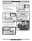
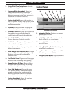
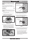
Installing and Adjusting Camlock
Studs
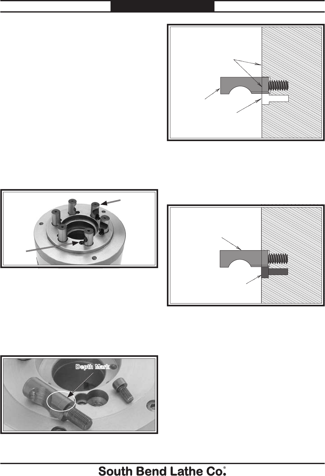
Figure 44. Identifying chuck camlock studs and
locking cap screws.
Locking
Cap
Screw
Cam-Lock
Stud
When fitting a chuck or faceplate with camlock
studs, or when mounting a new chuck or
faceplate, it may be necessary to install or adjust
the camlock studs.
Tool Needed Qty
Hex Wrench 6mm .................................................1
To install or adjust camlock studs onto a chuck or
faceplate:
1. Lay the chuck or faceplate upside down on a
protective, flat surface.
2. If installed, remove the locking cap screw
adjacent to each of the six cam-lock
mounting holes (see Figure 44).
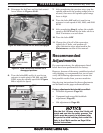
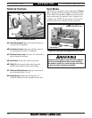
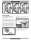
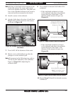
Camlock Stud Depth
Mark is Even with Chuck
or Faceplate Surface
Camlock Stud
Locking Cap
Screw Hole
Chuck/Faceplate
Figure 46. Initial adjustment of camlock stud.
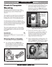
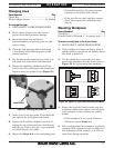
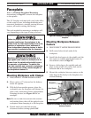
4. Install and tighten the locking cap screws.
5. Make sure that the cam-lock studs can
rotate back and forth against the head of the
locking cap screw (see Figure 47).
Camlock Stud Can
Rotate Back/Forth
Slightly
Cap Screw
Installed & Tight
Chuck/Faceplate
Figure 47. Camlock stud and cap screw correctly
installed.
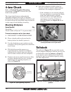
6. Insert the chuck onto the spindle, then check
the position of each camlock, making sure
the cam line points between the "V" marks.
— If one or more of the cams do not point
between the "V" marks on the chuck,
remove the chuck, and fine tune the
camlock stud adjustment by adjusting the
stud in or out and using Figure 48 on
the following page as a guide to correctly
position the cam lines.
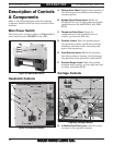
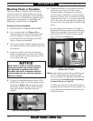
3. Thread each cam-lock stud into the chuck
or faceplate until the depth mark shown in
Figure 45 is even with the surface of the
chuck or faceplate and the curved indent
on the side of the stud faces the locking cap
screw hole, as shown in Figure 46. This is
an initial adjustment.
Figure 45. Example of camlock stud depth mark.
Depth Mark