


-46-
For Machines Mfg. Since 7/09
EVS Toolroom Lathes
OPERATION
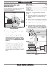
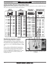
Understanding Thread & Feed Rate Chart
Figure 84 shows the configurations of gearbox levers that are required to set the available feed rates.
This same chart can also be found on the machine.
Figure 84. Thread and feed rate chart.
in.
Mod. D.P.
.2 LCT1Z
.225 LCT2Z
.25 LCT3Z
.3 LCT6Z
.35 LCT8Z
.4 LCS1Z
.45 LCS2Z
.5 LCS3Z
.6 LCS6Z
.7 LCS8Z
.75 LCT6Y
.8 LCR1Z
.9 LCR2Z
1.0 LCR3Z
1.1 LCR4Z
1.2 LCR6Z
1.25 LCS3Y
1.3 LCR7Z
1.4 LCR8Z
1.5 LCS6Y
1.75 LCS8Y
2.0 LCR1Y
2.5 LCR3Y
3.0 LCR6Y
3.5 LCR8Y
4.0 HCR3Z
4.5 HCS2Y
5.0 HCS3Y
5.5 HCS4Y
6.0 HCS6Y
6.5 HCS7Y
7 HCS8Y
8 HCR1Y
9 HCR2Y
10 HCR3Y
11 HCR4Y
12 HCR6Y
13 HCR7Y
14 HCR8Y
72 LAR6V
60 LAR3V
56 LBR8V
54 LAR2V
48 LBR6V
44 LBR4V
40 LBR3V
36 LAS6V
32 LBR1V
30 LAS3V
28 LBS8V
27 LAS2V
26 LBS7V
24 LBS6V
23 LBS5V
22 LBS4V
20 LBS4V
19 LCS2V
18 LBS2V
16 LBS1V
15 LAT3V
14 LBT8V
13½ LAT2V
13 LBT7V
12 LBT6V
11½ LBT5V
11 LBT4V
10 LBT3V
9 LBT2V
8 LBT1V
7½ HAS3V
7 HBS8V
6 HBS6V
5 HBS3V
4½ HBS2V
4 HBS1V
3¾ HAT3V
3½ HBT8V
3¼ HBT7V
3 HBT6V
2 7⁄8 HBT5V
2¾ HBT4V
2½ HBT3V
2¼ HBT2V
2 HBT1V
.3 HCT6Z
.4 HCS1Z
.5 HCS3Z
.6 HCS6Z
.7 HCS8Z
.8 HCR1Z
.9 HCR2Z
1.0 HCR3Z
1.25 HCS3Y
1.5 HCS6Y
1.75 HCS8Y
2.0 HCR1Y
2.25 HCR2Y
2.5 HCR3Y
2.75 HCR4Y
3.0 HCR6Y
3.25 HCR7Y
3.5 HCR8Y
44 HBR4V
40 HBR3V
36 HAS6V
32 HBR1V
30 HAS3V
28 HBS8V
26 HBS7V
24 HBS6V
22 HBS4V
20 HBS3V
19 HCS2V
18 HBS2V
16 HBS1V
15 HAT3V
14 HBT8V
13 HBT7V
12 HBT6V
11 HBT4V
10 HBT3B
9 HBT2V
8 HBT1V
.050 LCT1W .002
.055 LCT2W .0022
.065 LCT4W .003
.085 LCT8W .0033
.10 LCS2W .004
.13 LCS4W .005
.18 LCS8W .007
.22 LCR3W .009
.28 LCR4W .011
.35 LCR8W .014
.44 LCS8X .017
.55 LCR2X .022
.68 LCR3X .027
.85 LCR8X .033
1.2 HCS2X .047
1.4 HCS4X .055
1.7 HCS8X .067
mm
in.
mm
METRIC
THREADING
INCH
THREADING
MODULAR OR
DIAMETRAL
TURNING FEED RATE
(DIST./REVOLUTION)
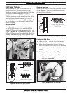
Figure 85. Gearbox levers set for a feed rate of 0.014"
(0.35mm).
Positioning Gearbox Levers
To cut a particular thread or establish a
particular feed rate, you may need to first swap
the gearbox drive gear, depending on where it is
currently set (refer to End Gear Setup on Page
47).
Once you have confirmed that the end gear is
set up properly, you can then move the gearbox
levers to the required positions. The arrows
going from Figure 84 to Figure 85 show which
gearbox levers must be moved to achieve an
example feed rate.