


-28-
For Machines Mfg. Since 7/09
EVS Toolroom Lathes
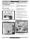
OPERATION
Mounting Chuck or Faceplate
The 4-jaw chuck is shipped with six camlock
studs that must be installed before the chuck
can be mounted, as explained in this procedure.
If you have not yet installed the camlock studs,
complete the instructions in "Installing and
Adjusting Camlock Studs" on Page 29.
To mount a chuck or faceplate:
1. DISCONNECT LATHE FROM POWER!
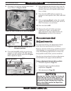
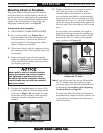
2. Lay a chuck cradle (see Figure 39) or
plywood under the chuck or faceplate and
over the bedway to protect the precision
ground surfaces from damage and reduce
injury if fingers get pinched.
3. Clean away debris and oily substances from
the mating surfaces of the spindle and chuck
or faceplate.
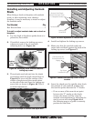
4. Inspect and make sure that all camlock
studs are undamaged, are clean and lightly
oiled, and that the camlock stud cap screws
are in place and snug.
Never install a chuck or faceplate without
having the camlock cap screws in place or
fully tightened. If you ignore this notice,
the chuck may not be removable since the
camlock studs may turn with the camlocks
and never release.
6. Tighten camlocks in a star pattern to draw
the chuck up evenly on all sides while
reducing chance of alignment, and make
sure to tighten camlocks in an incremental
manner to ensure that no camlock gets fully
tightened all at once (i.e., snug the camlocks
on the first pass, then moderately tighten on
the next pass, then fully tighten on the third
pass).
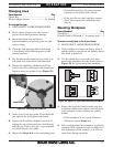
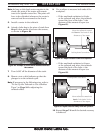
As you tighten the camlocks, the chuck or
faceplate will snug up onto the spindle nose.
When fully tightened, the cam line will fall
between the two "V" marks on the spindle
nose, as shown in Figure 43.
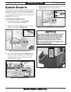
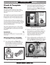
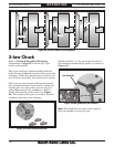
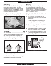
5. Position the chuck/faceplate in front of the
spindle nose, align the chuck timing marks,
as shown in Figure 42, and align the cam-
lock studs with the sockets, then carefully
insert the chuck or faceplate onto the
spindle.
Figure 42. Chuck timing marks aligned.
Chuck Timing Marks
Figure 43. Camlock fully tightened with the line
between the "V" marks.
Cam Line
Between
"V" Marks
Note: If any of the cam lines do not fall between
the "V" marks when the camlock is tight,
you must adjust the offending camlock stud
as discussed in Installing and Adjusting
Camlock Studs on Page 29.
To make sure that the chuck or faceplate is
perpendicularly aligned with the spindle, use
a test indicator mounted on the bedways to
check for runout.