


-24-
For Machines Mfg. Since 7/09
EVS Toolroom Lathes
OPERATION
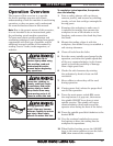
Refer to the following figures and descriptions
to become familiar with the basic controls of this
machine.
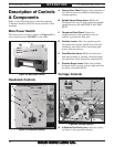
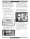
Main Power Switch
The main power switch is shown in Figure 33. It
turns master power ON/OFF to the lathe.
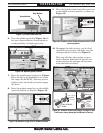
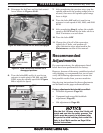
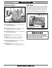
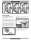
A. Change Gear Chart: Displays the positions of
the various gears for different threading or
turning options.
B. Spindle Speed Range Lever: Shifts the
headstock into low or high range for spindle
speeds between 20–400 RPM or 400–2500
RPM.
C. Thread and Feed Chart: Shows the
configurations of the gearbox levers to
achieve a particular feed rate.
D. Gearbox Levers: Move the gearbox gears
into particular ratios, which then turn the
leadscrew and feed rod for threading and
power feed operations.
E. Feed Direction Lever: Shifts the direction
that the gearbox is turning, which changes
the direction of the leadscrew and feed rod.
F. Gearbox Range Lever: Shifts the gearbox
between high, neutral, or low range and has
no effect on spindle RPM.
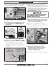
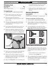
G. 4-Position Tool Post Lever: Locks the rotary
tool post in four possible detents.
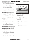
Carriage Controls
G
T
N
M
Q
R
S
I
P
H
Figure 35. Carriage controls.
O
K
L
J
Figure 33. Main power switch.
Main
Power
Switch
Headstock Controls
D
D
D
A
D
C
B
Figure 34. Headstock controls.
E
F
Description of Controls
& Components