


For Machines Mfg. Since 8/09 Model SB1019
-39-
SERVICE
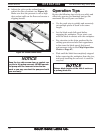
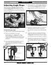
A blade that is perpendicular to the table surface
provides the best cutting results with minimal
side loading and blade wear. Frequently check
and adjust this setting.
To square the blade to the table:
1. DISCONNECT BANDSAW FROM POWER!
2. Separate the blade guides as far as possible,
then lower the bandsaw all the way until it
contacts the downfeed stop bolt.
3. Place a square on the table bed and against
the edge of the blade, as shown in Figure
41, then check different points along the
length of the table between the blade guides.
Squaring the Blade
4. If the blade is not square to the table, loosen
the cap screws shown in Figure 41 and
rotate the blade guide bearing assemblies as
necessary until the blade is perpendicular to
the bed, then re-tighten the hex bolts.
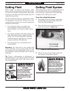
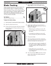
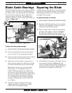
The blade guide bearings must support the blade
correctly to make cuts that are perpendicular to
the table surface. One bearing on each assembly
has an eccentric shaft that can be adjusted to
properly support the blade. The bearings are
secured in place by a hex nut and lock washer, as
shown in Figure 40.
Blade Guide Bearings
Figure 40. Blade guide adjustments.
Support Bearing
Eccentric
Shaft
Hex Nut &
Lock Washer
To adjust the blade guide bearings:
1. DISCONNECT BANDSAW FROM POWER!
2. Lift the headstock and close the downfeed
valve to stop it in the uppermost position.
3. Loosen the hex nuts that secure the eccentric
shafts attached to the guide bearings.
4. Adjust the eccentric shaft as necessary so
that it pushes against the blade just enough
to hold the blade flat between the bearings.
Note: Since the bearings twist the blade
into position, it is acceptable if there is
0.001"–0.002" gap between the blade and
the front or back of the bearing. Just make
sure not to squeeze the blade too tightly with
the bearings. After the guide bearings are
set, you should be able to rotate the guide
bearings (although they will be stiff) with
your fingers.
5. Adjust the support bearing in the same
manner, but leave a gap between 0.002–
0.003" from the back of the blade.
Figure 41. Squaring the blade.
Cap Screws
!
!