


MOVE THE SPOT SIZE CONTROL HANDLE on the large lens carriage to the forwardmost
position to project the smallest spot possible with the iris, choppers, and dimming controls in their full open
positions. Project the spot to a wall or similar flat perpendicular surface opposite the spotlight.
TURN THE CENTER FOCUS CONTROL counterclockwise until a small black spot is pro-
jected on the wall. It may be well to run this adjustment both directions to permit positive identification of the
dark spot.
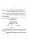
LOOSEN THE TWO THUMB SCREWS to the left and right of the focus control just enough
to permit manual movement of complete control assembly. Move the control assembly around the two thumb
screws and observe the smooth dark shadow of the bulb electrode inside the shaded circle of the reflector center
opening. The shadow of the electrode must be centered in the projected opening of the reflector.
MOVE THE CONTROL ASSEMBLY around the thumb screws until the dark electrode shadow
is as round as possible to project. It may be necessary to again rotate the focus control to define the electrode
shadow.
AFTER THE ELECTRODE SHADOW is as even around the outside as possible, tighten the
two thumb screws to lock this adjustment in place, and rotate the focus control to obtain the brightest light with
the best light distribution. Turn the spot focus control knob, located on the front of the lens mechanism, to
sharpen the edge of the spot.
THE SECOND METHOD of aligning the xenon bulb is to project the spot to the stage, and
using the bulb adjustment controls, obtain a “hot spot” in the projected spot. Center this “hot spot” in the
projected spot by moving the entire control section around the two thumb screws. Once the “hot spot” is
centered in the projected spot, lock the adjustment control in position with the two thumb screws and rotate the
focus control to obtain a spot with an even distribution of light. Turn the spot focus control knob at the front of
the lens mechanism to sharpen the edge of the spot.
THIS ADJUSTMENT should not be disturbed until the xenon bulb is rotated or replaced. At
this time it will be necessary to repeat the alignment procedure.
REPLACE THE REAR COVER PANEL over the bulb adjustment control mechanism.
Secure using the plastic fasteners.
BECAUSE OF MANUFACTURING TOLERANCES and normal bulb aging, it may be nec-
essary to operate one lamp at slightly higher or lower current than others to obtain equal light balance between
two or more spotlights. These adjustments are made at the xenon power supply.
TO EXTINGUISH THE ARC, place the LAMP switch in the OFF position. The blower in the
lamphouse will continue running until the xenon power supply is de-energized. Allow the blower to operate and
cool the bulb for at least five minutes after extinguishing.