


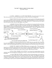
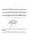

THE IRIS CONTROL is the front lever which projects through the top of the optical system
housing. When this lever is to the left (as viewed from the rear of the unit), the largest aperture is provided.
Smaller apertures are obtained as the lever is moved to the right.
THE SPOT SIZE CONTROL HANDLE is located on the right hand side of the optical system
just above the base rail. A variation of spot sizes from full flood to small spot can be obtained by moving the
spot size control handle from one extreme to the other. Beam intensity is increased by this optical system when
reducing from flood to spot, and maximum intensity is reached when the spot size control handle is in the
extreme forward position.
THE MAXIMUM FLOOD SPOT is obtained with the iris control lever to the left (away from
operating side) for the largest aperture and with the spot size control handle moved as far to the rear as possible.
SMALLER SIZED SPOTS are projected as the spot size control handle is moved forward.
Most of the spot sizes needed will be produced with the iris in its maximum open position.
FOR A “HEAD SPOT,” or any spot smaller than can be obtained with the spot size control
handle in its extreme forward position, shift the iris control lever to the right (toward operating side) for a
smaller aperture. The iris control lever should always be returned to its extreme left position before the spot size
control handle is again moved to obtain larger spots.
THE MASKING SHUTTER (chopper) lever is the middle lever projecting through the top of
the optical system housing. The masking shutter blades are operated by this lever to shape the projected spot to
a rectangle, strip spot, or dousing.
THE DISENGAGED POSITION of the masking shutter lever is to the extreme right (toward
operating side) and varying degrees of masking to complete cutoff are obtained by moving the lever to the left
(away from operating side).
THE ANGLE of the masking shutter blades can be adjusted to compensate for the horizontal
projection angle. Remove the color boomerang and optical system housing, and loosen the screws holding each
of the masking shutter blades enough to allow adjustments. Ignite the bulb and adjust the angle of the bottom
blade by tapping with a screwdriver so its projected edge lies parallel to the footlights. Tighten the screw.
Operate the masking shutter lever to close the blades. Adjust the upper blade to close in line with the bottom
blade and tighten the screw.
THE FADEOUT MECHANISM AND DOUSER CONTROL is the rear lever projecting
through the top of the optical system cover. This lever controls the intensity of light from complete fadeout
when the lever is to the left, to full intensity when the lever is to the right.
THE SPOT FOCUSING CONTROL KNOB is located on the operating side of the optical
system at the forward end above the base rail. This control is used to adjust the optical system for the length of
throw. When making an adjustment, rotate the spot focusing control knob until the sharpest edge is obtained on
the projected spot.
OPERATION OF OPTICAL SYSTEM