


700 WATT XENON BULB INSTALLATION
Type 48057 Trouper
CAUTION: OBSERVE ALL SAFETY PROCEDURES. Put on the protective face mask.
Wear clean cotton gloves to prevent marking the quartz envelope of the bulb with fingerprints.
REMOVE THE TOP COVER of the lamphouse by removing the four Holt head (tamperproof)
screws with the special screwdriver provided. Loosen the two knurled-head thumb screws (65152) on the front
bulb support yoke and pivot the retaining plate (65151) aside. Slide the 65131 clamp on the end of the igniter
lead over the brass socket of the rear bulb support collet (65844).
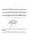
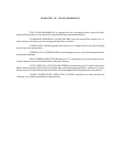
ASSEMBLE THE ADAPTERS to the 700 watt bulb prior to inserting the bulb into the lamp-
house. Be very careful not to apply any strain on the quartz envelope when installing adapters. Screw the
cathode adapter (65198) onto the threaded negative stud so it seats firmly against the shoulder of the (-) end cap.
Slip the 65259 anode adapter over the positive pin up to the shoulder of the (+) end cap. Tighten the set screw
(00720) securely to insure a good electrical connection.
REMOVE THE PLASTIC PROTECTIVE COVER from the xenon bulb only if necessary.
Insert the bulb through the top of the lamphouse, between the reflector support and the front casting. Pass the
anode (+) end of the bulb through the hole in the reflector, taking care not to touch the surface of the reflector.
INSERT THE ANODE ADAPTER STEM into the rear support collet. The stem must be
inserted as far as possible to permit full focus travel of the bulb. Place the cathode adapter into the 65117 front
bulb support, pivot the retaining plate to its closed position, and tighten the (2) thumb screws. Tighten the
socket head clamping screw in the anode contact securely to insure a good electrical contact.
INSTALL THE CATHODE LEAD CONTACT over the end of the cathode adapter up to the
shoulder of the contact and tighten the clamping screw securely. Lay the lead in front of the air duct to minimize
the shadow.
A GLASS STRIP HEAT FILTER is supplied to reduce the thermal energy at the optical sys-
tem and color gels. Insert the heat filter in the bracket provided on the inside of the lamphouse at the front
opening. Place the filter in position with the coated surface facing the bulb. The coated surface is indicated by
a small XX or other marking. This filter is a narrow strip that covers only the center portion of the beam. To
prevent damage to optical system components, do not operate the spotlight with the filter removed or reversed.
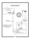
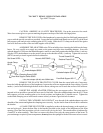
Anode Clamp
65131
Set Screw 00720
Rear Bulb Support Collet 65960
Anode Adapter 65259*
Hanovia XH0700HS
Front Bulb Support 65117
Cathode Adapter 65198
Thumb Screw 65152
Retainer Plate 65151
Clamping Screw 01532
* Use short adapter (65199) with OSRAM bulb