


TROUBLE CHART
NORMAL OPERATION
WHEN THE SWITCH in the main AC supply line to the xenon power supply is in the ON
position, and the 30 A. circuit breaker on the switching power supply is ON, the POWER light on the xenon
power supply will glow. The lamphouse blower will start. The blower in the power supply, if a older Strong
high reactance type (61000, 61001) or current production switching type, will operate.
IF THE LAMPHOUSE TOP COVER and access panel are correctly installed, the top and side
panel interlock switches will close. At this time, the control circuit to the LAMP switch will be completed.
THE MODE SWITCH, located on the lamphouse instrument panel, should be in the “MAN.”
(manual) position. This is the normal setting for spotlight opertion, as it allows direct ignition control by the
operator.
WHEN THE “LAMP” SWITCH is placed in the ON position, the AC control circuit in the
lamphouse will energize the power supply contactor circuit and provide DC current to the igniter and bulb. The
high DC open circuit voltage generated upon start-up of the power supply will actuate the DC Pulse Igniter.
THERE WILL BE a distinctly audible high voltage arc ping at the igniter arc gap and across
the bulb electrodes. The bulb should ignite immediately after one or two of these high voltage pulses, and the
lamp current will adjust to the output setting of the xenon power supply. Multiple ignition pulses prior to bulb
ignition normally indicate a low DC output setting. See xenon power supply manual. A “warm” or aged xenon
bulb might also require multiple strikes.
TROUBLE SHOOTING
IF THE XENON BULB does not ignite, observe the following operational sequences for assis-
tance in locating and isolating the trouble area.
WHEN THE FAN(S) and the indicator light on the power supply are on, the AC circuit in the
power supply is trouble free up to the terminal block in the power supply.
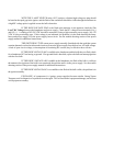
AT THIS TIME, the lamphouse blower should operate. If this does not occur, the trouble is in
the cover interlock switch, the access panel interlock switch, the blower motor, a loose connection, or a broken
#2 or #4 lead. Check at this time for 115 V.AC Control Voltage at the cover interlock switch (wires 2 & 4), the
side access panel (wires 13 & 14), and the blower terminals (9 & 12). The cover interlock switch must be
manually actuated to energize the blower. Observe caution when taking voltage readings in a power ON
condition.
THE VANE on the air flow switch should actuate. With the MODE switch in the “MAN.”
position and the LAMP switch in the “ON” position, the running time meter should start and indicate elapsed
time. If this meter does not operate, check for continuity at the MODE and LAMP switches. A defective
running time meter will not prevent bulb ignition.