


INSTALLATION & SET-UP
THE XENON TROUPER is shipped in sections which must be assembled. The Folding Base
Stand Assembly 65838 is shipped collapsed, and requires only unfolding and securing the (4) base legs using the
T-bolts supplied.
WHEN INSTALLED in a permanent location, the leveling feet must be removed, and the
clearance holes in the base leg brackets used for hardware (user supplied) to bolt the base to the floor or
platform. If it is desired to have the unit portable, when operating, the leveling feet must be adjusted down until
the weight of the spotlight has been shifted from the casters to the leveling feet.
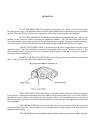
THE INNER TUBE and support yoke has three holes to permit adjusting the height of the
spotlight. The three holes are on four inch centers and will allow an optical height of approximately 53 inches,
57 inches, and 61 inches above floor level to the optical center of the lamphouse and lens system. The leveling
feet may be adjusted through an additional two inch range. Insert the height location pin through the hole in the
outer tube and one of the holes in the inner tube.
THE HORIZONTAL SWING and vertical tilt locking knobs are on the right hand (operating)
side of the yoke assembly. Tighten both of these locking devices securely before attempting to place the lamp-
house and lens system on the support yoke.
PLACE THE LAMPHOUSE and lens system on the yoke assembly, with the spot size control
handle to the right hand (operating) side, the same as the locking controls on the yoke. Line up the four
mounting holes in the bottom of the base rail with the four mating holes in the support yoke and secure with the
four 5/16-18 wing screws.
ATTACH THE COLOR BOOMERANG to the front of the optical system cover by inserting
the hinge pin through the hinge on the boomerang and optical system. Fasten the boomerang yoke to the slotted
angle bracket on the underside of the optical system pan. Adjust and securely tighten the wing nut and lock nuts
to hold the boomerang parallel with the front of the optical system housing.
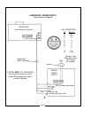
ATTACH THE LAMPHOUSE CABLE CONNECTOR to the receptacle on the power supply.
Align the pins before tightening the locking ring. Do not energize the xenon power supply before first installing
the xenon bulb into the lamphouse.
EARLIER MODELS of Strong xenon spotlights included a heavy-gauge green ground wire in
the lamphouse cable assembly. This ground wire was attached to a ground stud connected to the power supply
cabinet. Current models of Strong power supplies include a 1/4-20 stud in the cabinet adjacent to the MS
connector to allow ground termination of older spotlights.