


975-0395-01-01 xiii
This guide for use by qualified installers only
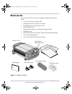
Figure 1-1 What’s In The Box - - - - - - - - - - - - - - - - - - - - - - - - - - - - - - - - - - - - - 1–2
Figure 1-2 Typical Recreational Vehicle and Fleet Vehicle Installation- - - - - - - - - - 1–6
Figure 1-3 Approved Mounting Orientations- - - - - - - - - - - - - - - - - - - - - - - - - - - - 1–13
Figure 1-4 DC Panel Connections - - - - - - - - - - - - - - - - - - - - - - - - - - - - - - - - - - - 1–14
Figure 1-5 Freedom HF AC Wiring Compartment - - - - - - - - - - - - - - - - - - - - - - - - 1–17
Figure 1-6 AC Wiring Diagram with an Inverter Subpanel - - - - - - - - - - - - - - - - - - 1–22
Figure 1-7 AC Wiring Diagram without an Inverter Subpanel - - - - - - - - - - - - - - - - 1–23
Figure 1-8 DC End - - - - - - - - - - - - - - - - - - - - - - - - - - - - - - - - - - - - - - - - - - - - - 1–24
Figure 1-9 DC Cable Connections- - - - - - - - - - - - - - - - - - - - - - - - - - - - - - - - - - - 1–27
Figure 1-10 Drip Shields - - - - - - - - - - - - - - - - - - - - - - - - - - - - - - - - - - - - - - - - - - 1–31
Figure 1-11 Typical Drip Shield Placement on a Freedom HF 1800 - - - - - - - - - - - - - 1–32
Figure 2-1 Dip Switches (Default Settings Shown) - - - - - - - - - - - - - - - - - - - - - - - 2–2
Figure 2-2 Display Panel - - - - - - - - - - - - - - - - - - - - - - - - - - - - - - - - - - - - - - - - - 2–3
Figure B-1 Typical Marine Installation- - - - - - - - - - - - - - - - - - - - - - - - - - - - - - - - B–3
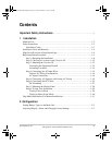
Figures
Freedom HF Install Guide.book Page xiii Friday, December 21, 2007 9:57 PM