


1–28 975-0395-01-01
This guide for use by qualified installers only
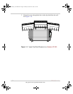
Step 7: Mounting the Display Panel
The communications cable supplied with the display panel is 25 feet (7.62
meters) long. If you want to replace the cable with one that is shorter, use
a high quality, 6-wire telephone extension cable.
Flush mounting the panel on a wall, bulkhead, or panel requires an
opening that is approximately 3.25 × 1.25 inches (8.25 × 3.18 cm). About
1.5 inches (3.81 cm) of free space is required within the wall to
accommodate the depth of the panel. Be sure there is no wiring or other
obstructions within the wall before you make an opening.
To mount the display panel:
1. Choose a location that is dry, out of direct sunlight, free from
corrosive or explosive fumes, and otherwise appropriate for mounting
an electronic device.
2. Tape the mounting template (in the Freedom HF package) to the
mounting surface and mark the locations of the mounting holes and
the area to be cut away.
3. Pilot-drill the mounting holes and cut out the hole in which the panel
will be inserted.
4. Route the communications cable(s) inside the wall and through the
opening.
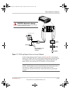
5. Insert one of the cable’s connectors in either jack on the bottom of the
panel.
6. Place the panel in the opening and secure it with appropriate
fasteners.
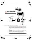
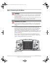
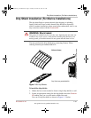
7. Route the communications cable to the Freedom HF and insert the
connector in the jack located near the battery select dip switch.
Important:
Do not route the communications cable in parallel and in conduit
with the AC and DC wires. In situations where the cable must cross with the AC
and DC wires, make sure they cross at a 90° angle to each other.
FreedomHF_IC_01-Installation.fm Page 28 Monday, December 24, 2007 9:47 AM