


B–2 975-0395-01-01
This guide for use by qualified installers only
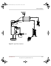
Marine Installation
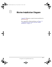
Figure B-1 illustrates a typical marine installation with the following
components:
1. AC power supplied from a shore power connector
2. An AC source panel that includes a Max 30A circuit breaker that
supplies the Freedom HF
3. An AC load panel with branch circuit breakers that supply only loads
that run off the Freedom HF
4. Engine negative bus / DC ground bus
5. DC power supplied by a battery bank and protected by a DC fuse in
the positive cable
6. Battery isolator
7. DC alternator
8. Starting battery
9. Drip shield (not shown)
Freedom HF Install Guide.book Page 2 Friday, December 21, 2007 9:57 PM