Basic Installation Procedures
975-0395-01-01 1–15
This guide for use by qualified installers only
Step 4: Connecting the AC Input Wires
General AC Wiring Considerations
AC Wiring
Connectors
Connect AC wires with crimp-on splice connectors.
The amount of insulation you strip off individual wires will be specified
by the connector manufacturer and is different for different types of
connectors.
AC and DC
Wiring
Separation
Do not mix AC and DC wiring in the same conduit or panel. Where DC
and AC wires must cross, make sure they do so at 90° to one another.
Consult applicable codes for details about DC and AC wiring in close
proximity to each other.
AC Wiring
Compartment
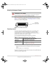
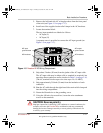
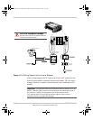
For your reference, the AC Wiring Compartment is shown in Figure 1-5.
AC Wiring and
GFCIs
You can plug loads (12 A continuous, 15 A maximum) directly into the
GFCI receptacle on the front panel of the Freedom HF. You can also
connect the inverter to an existing AC installation and then plug loads into
GFCI receptacles connected to that circuit.
If you plan to use the Freedom HF with the GFCI installed on the unit,
proceed to “Step 6: Connecting the DC Cables” on page 1–24.
If you plan to hard wire the Freedom HF AC input and output to an
existing AC installation, read this section.
AC wiring includes all the wires and connectors between the AC source
and the Freedom HF and all wiring between the inverter, the AC panels,
circuit breakers, and the GFCIs. The type and size of the wiring varies
with the installation and load. For some RV applications, flexible
multiple-strand wire is required.
WARNING: Fire, Shock and Energy hazards
Make sure wiring is disconnected from all electrical sources before handling. All
wiring must be done in accordance with local and national electrical wiring
codes. Do not connect the output terminals of the Freedom HF to any incoming
AC source.
FreedomHF_IC_01-Installation.fm Page 15 Monday, December 24, 2007 9:47 AM


