


1–16 975-0395-01-01
This guide for use by qualified installers only
AC wiring must be sized appropriately to carry full load current on the
input and output AC circuits in accordance with the electrical codes or
regulations applicable to your installation. Table 1-4 is based on the U.S.
National Electrical Code, 2003 Ed. and the Canadian Electrical Code,
assuming 2-conductor-plus-ground cable, using 75 °C wiring, at an
ambient temperature of 30 °C. Other codes and regulations may be
applicable to your installation.
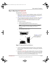
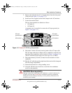
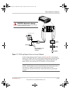
There are two knockouts on the front panel for AC input and output
wiring. Use the supplied strain relief clamps to prevent damage to the
wiring from tension being applied.
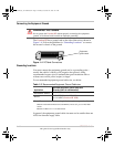
When making the AC input and AC output connections, observe the
correct color code for the appropriate AC wire, as described in Table 1-5.
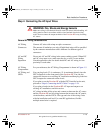
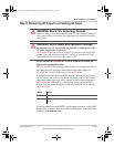
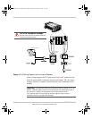
AC Input Connections
1. Ensure that AC and DC power are both OFF.
2. Install the required circuit breaker in the AC output panel supplying
the unit (See Figure 1-6 on page 1–22).
3. Remove the screws securing the GFCI AC receptacle and remove it
from the front panel.
4. Disconnect the GFCI wiring, if desired.
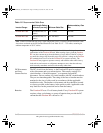
Table 1-4
Required AC wire size vs. required breaker rating
Required Breaker Size Required Wire Size
Freedom HF
30 A maximum 10 AWG
CAUTION: Equipment damage
The AC wiring terminal block is split into input and output sections. Damage to
the inverter will occur if the unit is wired incorrectly.
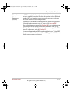
Table 1-5
Color codes for typical AC wiring
Color AC Wire
Black or Brown Line
White or Blue Neutral
Green, Green/Yellow,
or bare copper
Ground
FreedomHF_IC_01-Installation.fm Page 16 Monday, December 24, 2007 9:47 AM