


Basic Installation Procedures
975-0395-01-01 1–17
This guide for use by qualified installers only
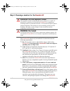
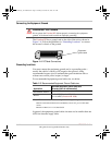
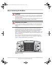
5. Remove the left-hand side AC wiring knockout from the front panel
of the unit (see Figure 1-5 on page 1–17).
6. Install one of the supplied strain-relief clamps in the AC knockout.
7. Locate the terminal block.
The two input terminals are labeled as follows:
• AC Input (L)
• AC Input (N)
A separate screw is provided to connect the AC input ground (see
Figure 1-5 on page 1–17).
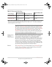
8. Strip about 2 inches (50 mm) from the jacket of the AC input cable.
The AC input cable may be either solid or stranded (as required), but
must have three conductors and be sized as in
Table 1-4 on page 1–16.
(The AC terminal block accepts wire sizes up to No. 10 AWG.)
9. Strip approximately 3/8 inch (10 mm) from the insulation of each
conductor.
10. Run the AC cable through the right-hand side strain-relief clamp and
into the wiring compartment.
11. Fasten the Ground wire to the grounding screw.
12. Using the 1/8 inch slot screwdriver, loosen the wire attachment
screws on the terminals.
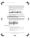
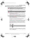
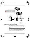
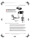
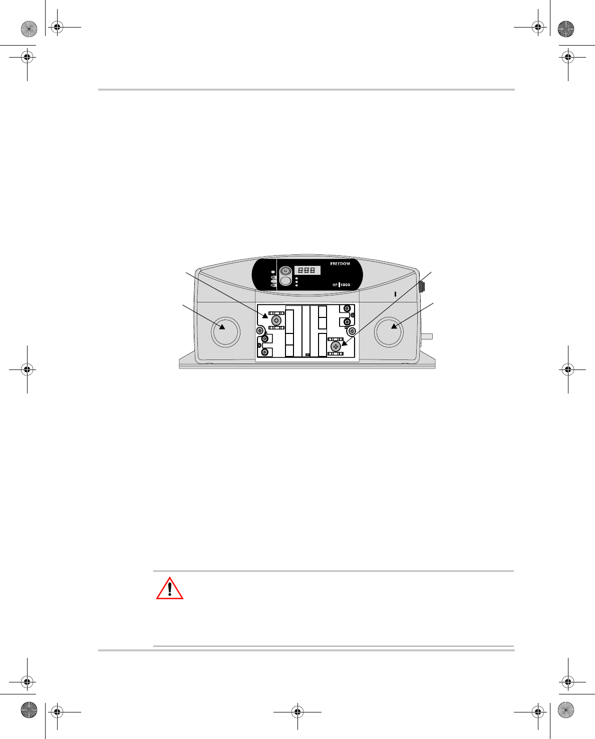
Figure 1-5
Freedom HF AC Wiring Compartment
Select
U tili ty
Battery
Fault
S TATUS
InputVoltage( V )
InputC ur ren t (A)
Output P ow er( W )
AC INPUT
N
L GND
AC OUTPUT
N
L GND
CAUTION!
Do not co nnect theAC OU T to any
other source of power. Damage to unit may occur.
FREEDOM HF1000
AC knockout
AC output
ground screw
AC input
ground screw
AC knockout
CAUTION: Reverse polarity
Improper connections (connecting a line conductor to a neutral conductor, for
example) will cause the Freedom HF to malfunction and may permanently
damage the inverter. Damage caused by a reverse polarity connection is not
covered by your warranty.
FreedomHF_IC_01-Installation.fm Page 17 Monday, December 24, 2007 9:47 AM