


1–20 975-0395-01-01
This guide for use by qualified installers only
To make a permanent connection to existing AC wiring (continuing
from # 15 of “Step 4: Connecting the AC Input Wires” on page 1–15):
1. Ensure that AC and DC power are both OFF.
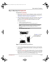
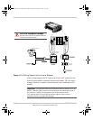
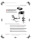
2. Install the required value of circuit breaker in the AC load panel (see
Figure 1-6 on page 1–22 and Figure 1-7 on page 1–23).
3. Remove the left-hand side AC wiring knockout from the front of the
unit.
4. Install one of the supplied strain-relief clamps in the AC knockout.
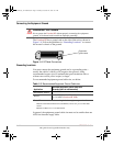
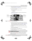
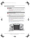
5. Locate the terminal block.
The two output terminals are labeled as follows:
•AC Output (L)
•AC Output (N)
A separate screw is provided to connect the AC output ground.
6. Strip about 2 inches (50 mm) from the jacket of the AC output cable.
The AC output cable may be either solid or stranded (as required), but
must have three conductors and sized as in Table 1-4 on page 1–16.
(The AC terminal block accepts wire sizes up to No. 10 AWG.)
7. Strip approximately 3/8 inch (10 mm) off the insulation of each
conductor.
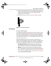
8. Run the AC cable through the left-hand side strain-relief clamp and
into the wiring compartment.
9. Fasten the Ground wire to the grounding screw.
10. Using the 1/8 inch slot screwdriver, loosen the wire attachment
screws on the terminals.
WARNING: Shock, fire, and energy hazards
Make sure wiring is disconnected from all electrical sources before handling. All
wiring must be done in accordance with applicable local and national electrical
wiring codes. Do not connect the output leads of the inverter to any incoming AC
source.
Important:
The applicable installation code may not allow you to run the AC
IN and AC OUT wiring through the same AC knockout.
FreedomHF_IC_01-Installation.fm Page 20 Monday, December 24, 2007 9:47 AM