


3-12 85054B
Use, Maintenance, and Care of the Devices
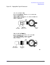
Gaging Connectors
Gaging the Sliding Load
Gage the sliding load before each use. If the sliding load pin depth is out of the observed
pin depth limits listed in Table 2-2 on page 2-4, refer to “Adjusting the Sliding Load Pin
Depth” on page 3-13.
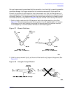
NOTE Always hold a connector gage by the gage barrel, below the dial indicator.
This gives the best stability, and improves measurement accuracy. (Cradling
the gage in your hand or holding it by the dial applies stress to the gage
plunger mechanism through the dial indicator housing.)
NOTE The sliding load uses a plastic centering bead to support its center conductor
when pin depth is adjusted and gaged and when the load is stored. Remove
this support bead from the sliding load before you connect the load for an
electrical calibration. Reinsert this support bead when you’ve finished using
the sliding load.
1. Select the proper gage for your connector. Refer to “Replaceable Parts for the 85054B
Calibration Kit” on page 6-2 for gage part numbers.
2. Inspect and clean the gage, gage master, and device to be gaged. Refer to “Visual
Inspection” on page 3-3 and “Cleaning Connectors” on page 3-4 earlier in this chapter.
3. Zero the connector gage as described in either Step 3 on page 3-8 (for a male gage) or
Step 3 on page 3-10 (for a female gage)
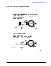
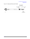
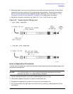
4. Remove the center conductor protective cap from the sliding load.
5. Loosen the center conductor pull-back nut completely, and press the center-conductor
cap to extend the center conductor beyond the end of the connector. With the sliding
ring pulled back approximately 0.5 inch, install a centering bead (if not already
installed) in the connector end of the sliding load.
6. Continue to press the center conductor cap and mate the center conductor of the sliding
load with the gage’s center conductor.
CAUTION The sliding load center conductor can be damaged if the sliding load is not
held in line when mating the load to a connector. Always line up the sliding
load when connecting or removing it from a connector.
7. Mate the outer conductor of the sliding load with the outer conductor of the gage.
Torque the connection with a 3/4 inch torque wrench to approximately 135 N-cm
(12 in-lb). Retighten the center conductor pull-back nut. It will “click” when it is tight.
8. Gently tap the barrel of the gage with your finger to settle the gage reading.
9. Read the gage indicator dial. If the needle had moved clockwise, the center conductor is
protruding and the value is determined by the black numbers. If the needle had moved
counterclockwise, the center conductor is recessed by an amount determined by the red
numbers.
10.For maximum accuracy, measure the connector a minimum of three times and take an
average of the readings.