


A-12 85054B
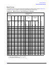
Standard Definitions
Nominal Standard Definitions
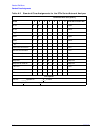
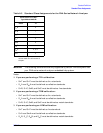
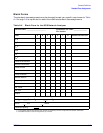
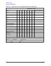
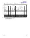
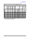
Table A-7 Standard Definitions for the 8510 Network Analyzer
System Z
0
a
= 50.0
Ω
Disk File Name:
CK_NTYPB2
Calibration Kit Label: TYPE N B.2
File Number: * FILE 1
Standard
b
C0
×
10
−15
F
C1
×
10
−27
F/Hz
C2
×
10
−36
F/Hz
2
C3
×
10
−45
F/Hz
3
Fixed or Sliding
c
Offset
Frequency
in GHz
d
Coax or Waveguide
Standard Label
Number
Type
L0
×
10
−12
H
L1
×
10
−24
H/Hz
L2
×
10
−33
H/Hz
2
L3
×
10
−42
H/Hz
3
Delay
Z
0
Ω
Loss in G
Ω
/s
Min
Max
1
Short
e
−
0.1315
606.21 −
68.405
2.0206
27.990 50 1.3651 0 999 Coax
Short (m)
f
2
Open
e104.13
−
1943.4
144.62 2.2258
22.905 50 0.93 0 999 Coax
Open (m)
f
3
Short
e 0.7563 459.88
−
52.429 1.5846 63.078 50 1.1273 0 999 Coax
Short (f)
f
4
Open
e 89.939 2536.8
−
264.99 13.4 57.993 50 0.93 0 999 Coax
Open (f)
f
5
6
7
8
9 Load Fixed 0 50 0 0 999 Coax Broadband
10 Load Sliding 0 50 0 1.999 999 Coax Sliding
11 Delay/
thru
05000999CoaxThru
12 Load Fixed 0 50 0 0 2.001 Coax Lowband
13 Delay/
thru
134.82 50 2.2 0 999 Coax f-f adapter
14 Delay/
thru
196 50 2.2 0 999 Coax m-m
adapter
15
16
17
18
19
20
21
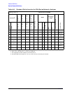
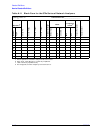
a. Ensure system Z
0
of network analyzer is set to this value.
b. Open, short, load, delay/thru, or arbitrary impedance.
c. Load or arbitrary impedance only.
d. For waveguide, the lower frequency is the same as F
CO.
e. Typical values only. Disk values may be different.
f. Standard labels which specify ex, (m) or (f), refer to the sex of the test port connector.