


3-18 85054B
Use, Maintenance, and Care of the Devices
Connections
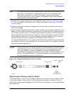
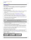
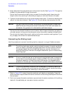
3. Apply downward force perpendicular to the wrench handle. See Figure 3-8. This applies
torque to the connection through the wrench.
Do not hold the wrench so tightly that you push the handle straight down along its
length rather than pivoting it, otherwise you apply an unknown amount of torque.
4. Tighten the connection just to the torque wrench break point. The wrench handle gives
way at its internal pivot point. See Figure 3-8. Do not tighten the connection further.
CAUTION You don’t have to fully break the handle of the torque wrench to reach the
specified torque; doing so can cause the handle to kick back and loosen the
connection. Any give at all in the handle is sufficient torque.
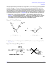
Do not pivot the wrench handle on your thumb or other fingers, otherwise you apply an
unknown amount of torque to the connection when the wrench reaches its break point.
Do not twist the head of the wrench relative to the outer conductor mating plane. If you
do, you apply more than the recommended torque.
Connecting the Sliding Load
Use this procedure to connect the sliding load to a test port or a type-N cable connector.
NOTE The sliding load uses a plastic centering bead to support its center conductor
when pin depth is adjusted and gaged and when the load is stored. Remove
this support bead from the sliding load before you connect the load for an
electrical calibration. Reinsert this support bead when you’ve finished using
the sliding load.
CAUTION Circuitry inside the test set at the test ports may be destroyed if precautions
are not taken to avoid electrostatic discharge (ESD). During this procedure,
the center conductor of the sliding load is connected to the exposed center
conductor of the test port. Ground yourself to prevent electrostatic discharge.
CAUTION The sliding load center conductor can be damaged if the sliding load is not
held in line when mating the load to a connector. Always line up the sliding
load when connecting or removing it from a connector.
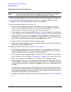
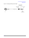
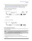
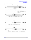
1. Refer to Figure 3-9. Loosen the center conductor pull-back nut completely. Press the
center conductor cap to extend the center conductor of the sliding load beyond the end of
the connector.
2. Continue to press the center conductor cap and mate the center conductor of the sliding
load with the cable/test port connector’s center conductor.