


Quick Start Guide 2-13
ESG Family Signal Generators Exploring the User Interface
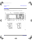
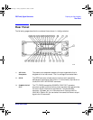
Rear Panel
12. PATTERN
TRIG IN
This input can accept either a TTL/CMOS low to TTL/CMOS high or
TTL/CMOS high to TTL/CMOS low edge trigger. With Option UN8
this input triggers the internal digital modulation pattern generator
to start a single pattern output or to stop and re-synchronize a
pattern that is being continuously output. With Option UND this
input is the external trigger source for all ARB waveform generator
triggers. With Option 201 this connector is used for system reset
trigger input.
13. BURST GATE
IN
The BURST GATE IN connector accepts a TTL or CMOS signal for
gating burst power in digital modulation applications. This female
BNC connector is present only on instruments with Options UND or
UN8. With Option 201 this connector is used for even second
synchronization input.
14. COHERENT
CARRIER OUT
This connector outputs RF that is not modulated with AM, pulse, or
I/Q modulation, but that is modulated with FM or ΦM. This SMA
connector is present only on ESG-D and ESG-DP Series Signal
Generators.
15. ALT PWR IN This BNC connector accepts a CMOS signal for synchronization of
external data and alternate power signal timing. This connector is
active only with Options UNA or 201. With Option 201 this
connector is used for Long Code State Latch strobe input.
16. EVENT 1 With Option UN8 turned on, this TTL/CMOS-compatible connector
outputs a pulse that can be used to trigger the start of a data
pattern, frame, or timeslot. With Option UN5 turned on, an even
second output is generated every two seconds indicating the
beginning of each short code sequence. With Option UND turned on,
a marker is output whenever a Marker 1 is turned on in the
waveform. With Option 201 you can select from several different
output signals for this connector.
17. EVENT 2 This TTL/CMOS-compatible connector outputs a data enable signal
for gating external equipment. With Option UN5 turned on, a
marker is output every 26.67 ms, corresponding to the start of each
short code. With Option UND turned on, a marker is output
whenever a Marker 2 is turned on in the waveform. With
Option 201 this connector is used for system reset output.
qsg.book Page 13 Friday, September 22, 2000 3:13 PM