2-14 Quick Start Guide
Exploring the User Interface ESG Family Signal Generators
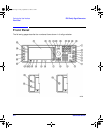
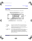
Rear Panel
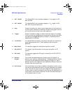
18. BASEBAND
GEN REF IN
With Option UN8 enabled, the BASEBAND GEN REF IN connector
accepts a 0 to +20 dBm sinewave or TTL squarewave signal from an
external 13-MHz timebase reference. This female BNC connector is
present only on instruments with Options UND or UN8.
19. I OUT The I OUT connector outputs the analog, in-phase component of I/Q
modulation from the internal baseband generator. This female BNC
connector is present only on instruments with Options UND or
UN8.
20. Q OUT The Q OUT connector outputs the analog, quadrature-phase
component of I/Q modulation from the internal baseband generator.
This female BNC connector is present only on instruments with
Options UND or UN8.
21. BER MEAS
END
The BER MEAS END connector outputs a signal that indicates the
status of the bit-error-rate (BER) measurements. This female SMB
connector is present only on instruments with Option UN7.
22. BER TEST OUT The BER TEST OUT connector outputs a signal that indicates the
test result of the pass/fail judgement of the bit-error-rate
measurements. This female SMB connector is present only on
instruments with Option UN7.
23. BER ERR OUT The output of the BER ERR OUT connector is normally low. When
the maximum data rate mode is set to 2 Mbps, the BER ERR OUT
connector outputs pulse signals that indicate errors. This female
SMB connector is present only on instruments with Option UN7.
24. BER NO DATA The BER NO DATA connector outputs a signal that indicates the
“no data” status. The no data status is reported when there has been
no clock input for more than 3 seconds or there has been no data
change for more than 200 bits. This female SMB connector is
present only on instruments with Option UN7.
25. BER SYNC
LOSS
The BER SYNC LOSS connector outputs a signal that indicates the
synchronization loss state. This female SMB connector is present
only on instruments with Option UN7.
qsg.book Page 14 Friday, September 22, 2000 3:13 PM


