


STEP 4. Clean the table top.
Before proceeding with the assembly of your saw, it is recommended that you clean the table-
top to remove the rust preventive coating. Clean the top with mineral spirits or denatured alco-
hol.
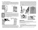
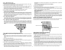
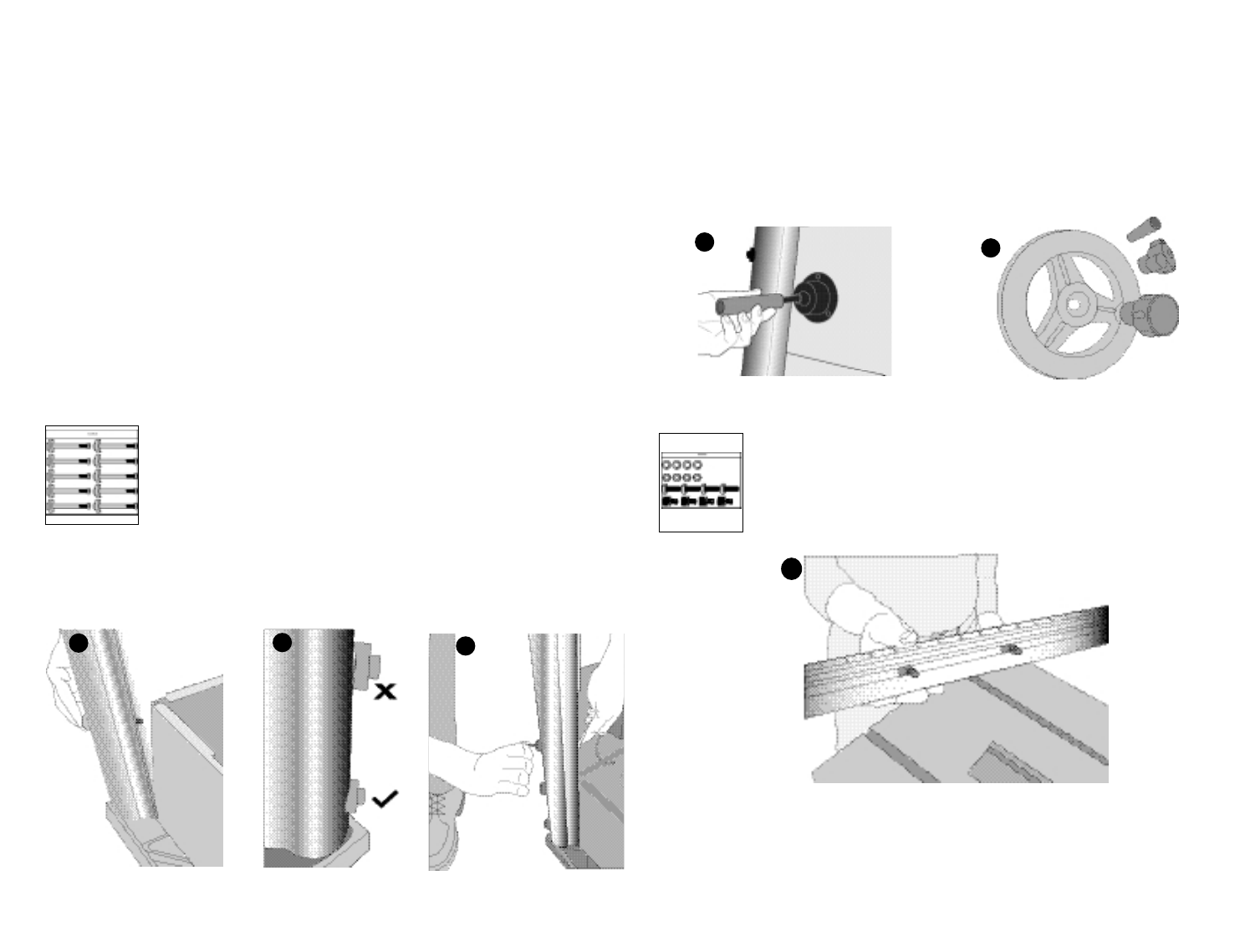
STEP 5. Handwheel assembly (Figures 4,5)
Bevel Adjustment Wheel (Right side of saw) Attach the sleeve (part K packed in styro-
foam) to the shaft that extends from the side of the table saw as shown in Figure 4. Align
the flat portion on the inside of the handwheel (part J) with the flat portion on the shaft.
Thread on the handwheel lock knob (part L) but do not tighten at this time. NOTE: Lock -
knobs are for locking height and bevel settings once they are established.
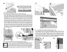
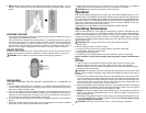
STEP 6. Attach the right front rail (long section) to tabletop (Figure 6)
Insert two of the square head bolts from the front and rear rail hardware bag
shown to the left, into the channel of the front rail as shown in Figure 6. Align the
two bolts with the two holes on the right side of the tabletop. Push the bolts
through the holes and loosely attach a lockwasher and hex nut onto the bolts.
Slide the front rail to the right far enough to expose the two holes on the left side
of the tabletop.
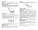
STEP 7. Attach the left front rail to tabletop (Figures 7,8)
Insert two of the square head bolts into the channel of the left front rail as shown in Figure
7. Align the two bolts with the two holes on the left side of the tabletop. Push the bolts
through the holes and loosely attach a lockwasher and hex nut onto the bolts. Slide both
sections of the front rails together and insert the black coupler on the left rail into the right
rail as shown in Figure 8. At this time, move the front rail assembly so that the section
where the two rails meet is approximately in line with the saw blade.
6
Assembly for BT2500
PLEASE READ ENTIRE ASSEMBLY SECTION
BEFORE PROCEEDING.
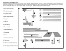
TOOLS INCLUDED
To aid you with assembly of your new saw,
we have included the following tools.
• 6mm Allen Wrench
• 12mm/10mm Combination Wrench
• (2) Blade Wrenches
TOOLS YOU WILL NEED TO SUPPLY
• Phillips screwdriver
• Combination Square
You will also need:
• Mild solvent cleaner such as mineral spirits, paint thinner or denatured alcohol.
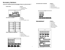
STEP 1. Remove parts bags and all component parts from the carton and check the contents
against the parts illustrated on pages 5 and 6.
STEP 2. Remove the saw from the box and leave it in an upside down position. You may need
help. The combined weight of the table top and motor assembly is approximately 100 lbs.
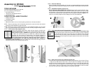
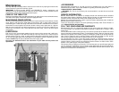
STEP 3. Install the four legs. (Figures 1,2,3)
With the saw assembly upside down, attach the legs using the 10 bolts in the
leg stand hardware bag shown to the left. Insert the bolt through the hole in
the leg as shown in Figure 1. (NOTE: All four legs are the same. The front legs
use 3 bolts each and the back legs use 2 bolts each.) With the bolt inserted
through the leg, insure that the curved portion of the plastic positioner is
aligned with the curve of the leg as shown in Figure 2. Using the supplied hex
wrench and the supplied 12mm wrench, attach the legs as shown in Figure 3.
NOTE: DO NOT OVERTIGHTEN. THE LEGS ARE HOLLOW AND WILL INDENT IF
EXCESSIVE FORCE IS USED. Place the 4 rubber feet on the ends of the legs and have
someone help you turn the assembly right side up.
1
2
3
7
4
5